Stopper for reliable gas injection

a stopper and gas injection technology, applied in the direction of liquid transfer devices, manufacturing tools, manufacturing converters, etc., can solve the problems of air suction into the gas stream, significant detriment to the quality of the metal being cast, and slit-like paths

Inactive Publication Date: 2007-04-03
VESUVIUS USA CORP
View PDF7 Cites 12 Cited by
  • Summary
  • Abstract
  • Description
  • Claims
  • Application Information

AI Technical Summary

Benefits of technology

[0009]The predetermined resistance to flow of the gas passages extending along the rod is calculated to permit a very precise and reliable control of the relationship gas-flow / internal pressure and / or to maintain a positive gas pressure within the stopper.
[0010]The use of such a rod which can be inserted into the stopper body at the very end of the manufacturing process of the stopper permits an extreme flexibility in the setting up of the “predetermined” resistance to flow so that the stopper of the invention can be adapted to a wide range of operational parameters simply by changing the rod. Furthermore, the rod—being manufactured separately—can received much more attention than if made together with the stopper and is therefore much more reliable. Such rods are available commercially for use as thermocouple sheaths.
[0011]Preferably, the rod is made from a gas-impermeable refractory material so that gas leaks at the level of the rod are avoided, thereby increasing the reliability of the calibration. Advantageously, the material is also wear-resistant so that the predetermined resistance to flow remains constant during the entire life of the rod. Suitable materials include mullite, a fired alumino-silicate, alumina re-crystallised alumina, zirconia-alumina and other high-refractory materials having the required properties.

Problems solved by technology

Problems have been encountered with sealing such systems and ensuring that the gas follows its intended path and is not wasted.
One such problem is apparent due to the effect during pouring of large volume of melt of metal flowing past the nose of the stopper through the discharge nozzle.
A negative pressure can be generated at the stopper tip which can be transmitted through the gas discharge port into the body and back to the supply pipework where it may exploit any inadequate joints causing air suction into the gas stream with significant detriment to the quality of the metal being cast.
However, these systems suffer from the problem of changes in the permeable metal comprising a stopper body having an internal chamber and a gas discharge port, a bore connecting the internal chamber to the gas discharge port, calibrating means being provided in the bore to provide a restricted path.
However, the formation of a slit-like path made by using a sacrificial void former is extremely unreliable and does not allow the formation of a restriction with a precise predetermined resistance to flow.
Further, this formation method does not allow the formation of very narrow passages.
Such a design of the calibrating means does not permit flexibility in the manufacturing process.

Method used


Image

  • Stopper for reliable gas injection
  • Stopper for reliable gas injection

Examples


Embodiment Construction

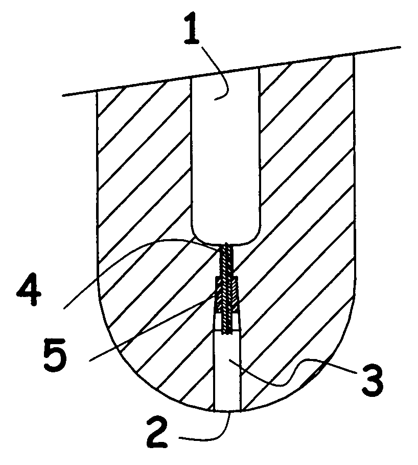
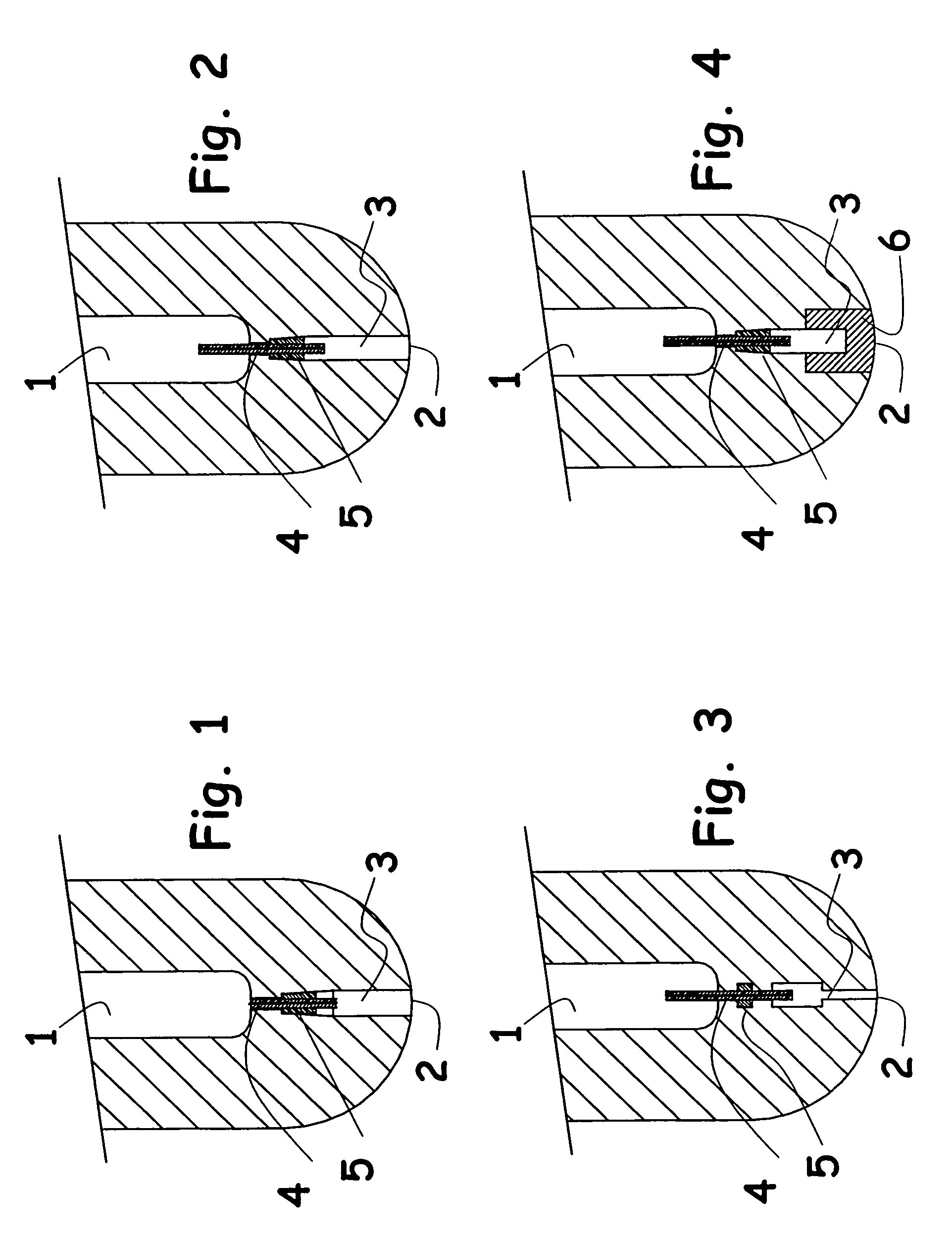
[0016]The predetermined resistance to flow of the gas passages extending along the rod is calculated to permit a very precise and reliable control of the relationship gas-flow / internal pressure and / or to maintain a positive gas pressure within the stopper.

[0017]The use of such a rod which can be inserted into the stopper body at the very end of the manufacturing process of the stopper permits an extreme flexibility in the setting up of the “predetermined” resistance to flow so that the stopper of the invention can be adapted to a wide range of operational parameters simply by changing the rod. Furthermore, the rod—being manufactured separately—can received much more attention than if made together with the stopper and is therefore much more reliable. Such rods are available commercially for use as thermocouple sheaths.

[0018]Preferably, the rod is made from a gas-impermeable refractory material so that gas leaks at the level of the rod are avoided, thereby increasing the reliability ...


PUM

PropertyMeasurementUnit
heightaaaaaaaaaa
heightaaaaaaaaaa
resistanceaaaaaaaaaa

Abstract

The present invention concerns a mono-block stopper adapted to deliver gas during pouring of molten metal comprising a stopper body having an internal chamber (1) and a gas discharge port (2), a bore (3) connecting the internal chamber (1) to the gas discharge port (2), calibrating means (4) being provided in the bore (3) to provide a restricted path. This stopper is characterised by the fact that the calibrating means comprise a rod (4) having at least one axially-extending gas passages therealong, the gas passage(s) having a section such as to offer a predetermined resistance to flow. The stopper of the invention is far more reliable and can be easily adapted to various operational parameters.

Description

FIELD OF THE INVENTION[0001]This invention relates to a mono-block stopper rod used to control the flow of molten metal from a discharge nozzle in a holding vessel during metal teeming.BACKGROUND OF THE INVENTION[0002]In continuous casting processes, the use of gases injected down the stopper has been shown to have significant benefits on the quality of metal being cast. For example, inert gases such as argon or nitrogen can be injected to reduce the problems due to alumina build-up and clogging or to assist in removing solidification products from the vicinity of the discharge nozzle. Reactive gases may also be employed when the melt composition needs modifying. Conventionally, the stopper is provided with an internal chamber connected to gas supply means on the one end and to a gas discharge port at the other end.[0003]Various systems have been developed to ensure an accurate measured flow of gas is supplied to the stopper. Problems have been encountered with sealing such systems ...

Claims


Application Information

Patent Timeline
Patent Type & Authority Patents(United States)
IPC IPC(8): C21C5/30B22D11/10B22D41/16B22D41/18B22D41/42C04B35/101
CPCB22D41/186B22D41/18
Inventor RICHARD, FRANCOIS-NOELHANSE, ERIC
Owner VESUVIUS USA CORP
Why Eureka
Try Eureka