
Optimal speed management for reaction wheel control system and method

a technology of reaction wheel and control system, applied in the field of spacecraft attitude control, can solve the problems of limiting the service life of the spacecraft, undetectable dependence, and small available torque, so as to minimize the need for momentum dumping, minimize the infinity norm of the wheel speed vector, and minimize the maximum speed of rotation of all the reaction wheels

Active Publication Date: 2007-04-03
LOCKHEED MARTIN CORP
View PDF4 Cites 15 Cited by
  • Summary
  • Abstract
  • Description
  • Claims
  • Application Information

AI Technical Summary

Benefits of technology

[0014]Described is spacecraft implementing a novel reaction wheel assembly speed management system and method in which need for momentum dumping is minimized. The system comprises an attitude controller configured for sensing three-dimensional attitude of the spacecraft and producing torque control signals for stabilizing the spacecraft in a prescribed three-dimensional attitude in space, and at least four mutually skew reaction wheels which are rotated in response to the torque control signals for applying the control torques and storing three-dimensional angular momentum. Reaction wheel speed measuring devices are employed for generating reaction wheel speed signals, and a reaction wheel speed control processor, responsive to the torque control and reaction wheel speed signals, produce reaction wheel spin control signals so as to redistribute a desired three-dimensional stabilizing momentum to the spacecraft in all RWAs in such a manner that the maximum speed of rotation of all the reaction wheels at any moment, is minimized.
[0015]In accord with an aspect of the disclosure, the reaction wheel speed control processor causes the nullspace vector components of the reaction wheel speeds to move towards specified values, that may be computed in order to minimize the infinity norm of the wheel speed vectors.
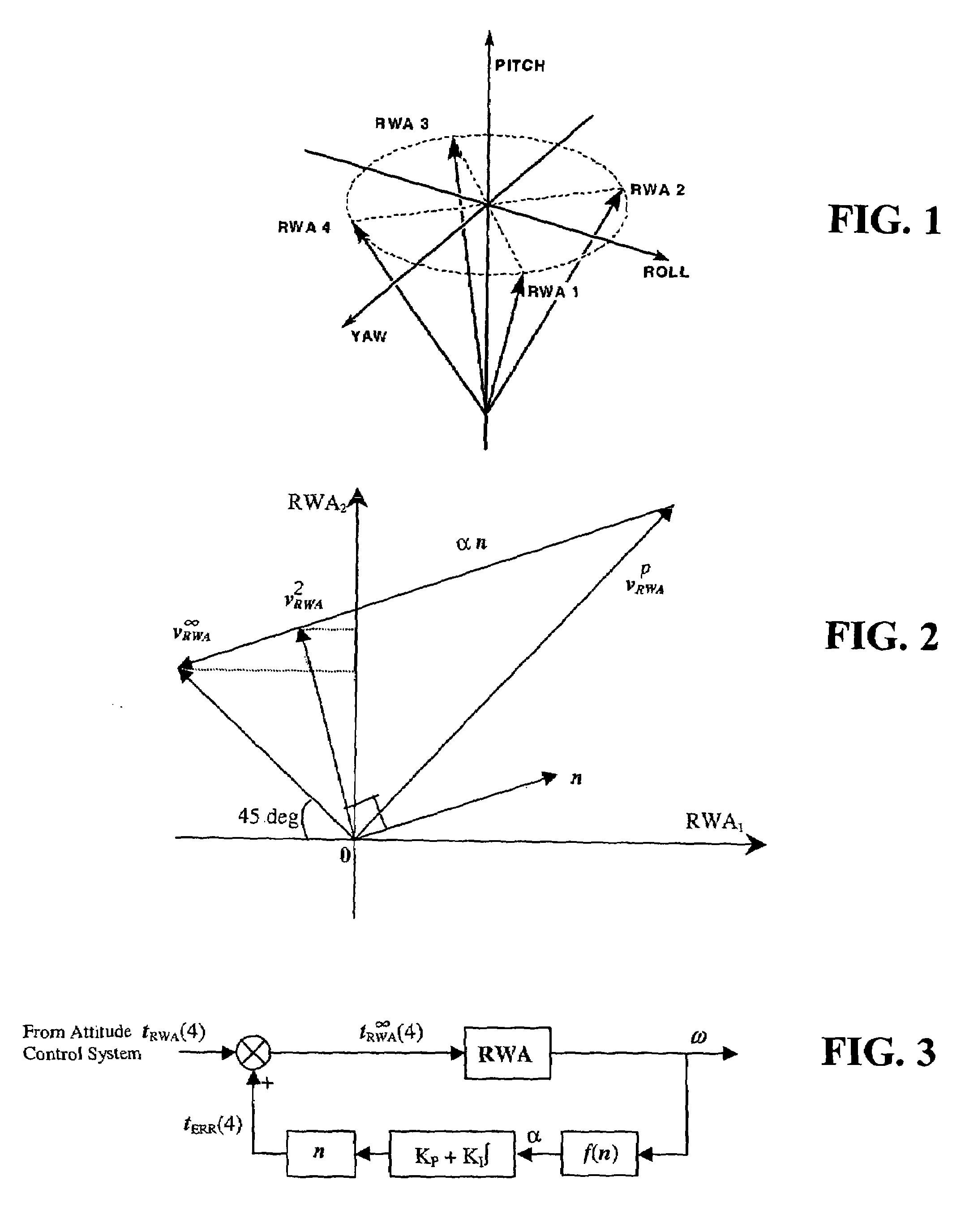
[0016]A method of implementing optimal speed management, in accord with the disclosure, comprises sensing the attitude of the spacecraft to produce attitude signals, processing the attitude signals to produce torque control signals representative of the torques required to maintain the spacecraft stabilized at a prescribed three-dimensional attitude in space, and spinning at least four mutually skewed reaction wheels on the spacecraft in response to the torque control signals. Speeds of the wheels are sensed to produce wheel speed signals, which in an exemplary embodiment may be processed based on an infinity-norm optimization algorithm and the nullspace vector to compute, from reaction wheel speed, an error torque for varying the torque control signals for individual wheels. This error torque may be applied so as to redistribute a desired three-dimensional momentum of the spacecraft among all RWAs in such a manner that the maximum speed of rotation of all the reaction wheels is minimized.

Problems solved by technology

Three-axis stabilization may be accomplished by a control system using fuel-burning thrusters, but the use of such thrusters requires the expenditure of fuel, which tends to limit the service life of the spacecraft.
Magnetic torquers have the disadvantages that the available torques tend to be small, and undesirably dependent upon the local magnitude of the magnetic field of the heavenly body being orbited.
In cases where number of wheels is four or more, the total spacecraft momentum can be stored in the set of wheels in infinitely many ways due to the under-determined nature of the problem, or the existence of the wheel null-space.
This system monitors the wheel speeds and generates a wheel speed error vector.
The drawback of the methods is that simply minimizing maximum energy into the system does not minimize the maximum speed of the fastest of the reaction wheels, and hence does not provide the longest possible periods between momentum dumping maneuvers.
This results in more than necessary fuel consumption and active ground involvement.

Method used


Image

  • Optimal speed management for reaction wheel control system and method
  • Optimal speed management for reaction wheel control system and method
  • Optimal speed management for reaction wheel control system and method

Examples


Embodiment Construction

[0022]The 2-norm and infinity-norm of a n-dimensional vector v=[v1 v2 . . . vn]T are defined respectively as

[0023]v2=∑in⁢vi2=vT⁢v(1)v∞=max⁢{vi:i=1,2,…⁢,n}(2)

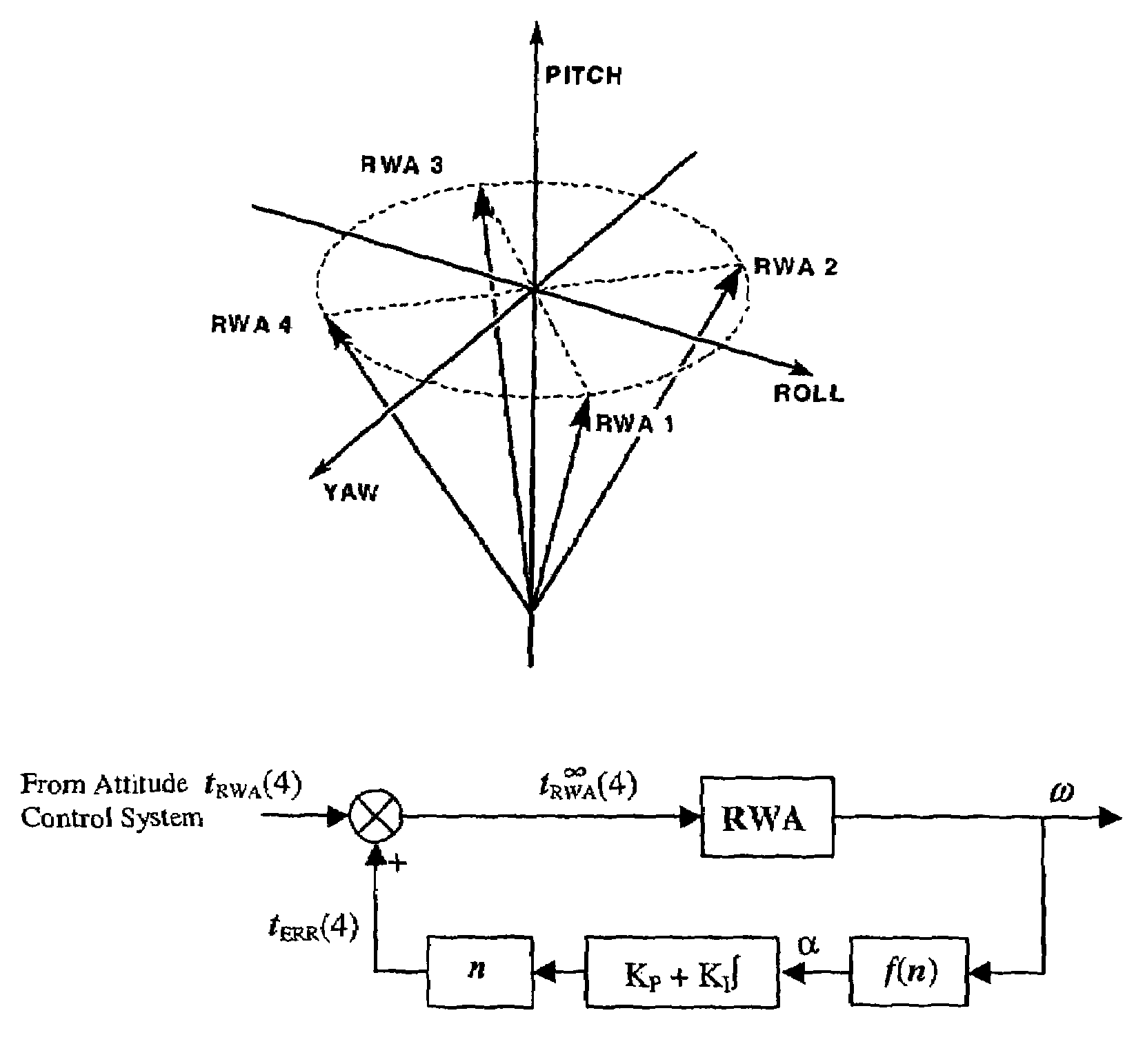
[0024]In the remainder of the disclosure, a four-wheel configuration is assumed for simplicity in the description of the invention. It is straight forward to extend the disclosure herein to apply to systems containing a greater number of wheels. FIG. 1 shows a typical orientation of 4 wheels with respect to the spacecraft body frame.

[0025]Based on the mount orientation, the RWAs to the spacecraft body transformation can be formed as

T=[r1 r2 r3 r4]  (3)

where ri is the ith wheel spin unit vector (direction of the wheel spin) expressed in the spacecraft body frame. The relationship between individual wheel momentum vector vRWA and the net momentum vector vsc in the spacecraft body frame is given by

vSC=TvRWA  (4)

[0026]Since T is a full row-rank 3×4 matrix, there exists infinity number of ways vRWA can be calculated corresponding to ...


PUM


Abstract

A spacecraft attitude control system and method in which an attitude controller is configured for sensing three-dimensional attitude of the spacecraft, and producing torque signals for stabilizing the spacecraft in a prescribed attitude in space. At least four mutually skew reaction wheels are rotated in response to the torque control signals for storing three-dimensional angular momentum, and speeds of rotation of the wheels are measured. A reaction wheel speed control processor, responsive to reaction wheel torque and speed for producing reaction wheel spin control signals, implements an infinity-norm algorithm for causing the nullspace components of wheel speed to re-distribute a desired three-dimensional stabilizing momentum of the spacecraft in such a manner that the maximum speeds of rotation of all the reaction wheels is minimized. As a result, periods between successive momentum dumping maneuvers are prolonged to the maximum possible.

Description

TECHNICAL FIELD[0001]This disclosure relates generally to spacecraft attitude control, and more particularly to a novel attitude control system and method in which momentum is distributed optimally among four or more on-board reaction wheels.BACKGROUND OF THE DISCLOSURE[0002]Orbiting spacecraft are used for a large variety of sensing and communication applications. For photographic purposes, it may be desirable for the spacecraft to be relatively near the Earth, so that the cameras or sensors are close to the subjects. For communication purposes, a geosynchronous equatorial orbit is often desirable. Whatever the orbit, a satellite must be stabilized in space if the sensors or antennas are to be pointed in appropriate directions.[0003]Spacecraft attitude stabilization may be accomplished by spinning the spacecraft and by mounting the sensors or antennas on a despun platform. Alternatively, the spacecraft may be stabilized in three axes. Three-axis stabilization may be accomplished by...

Claims


Application Information

Patent Timeline
IPC IPC(8): B64G1/28
CPCB64G1/283B64G1/285B64G2001/245B64G1/245
Inventor RATAN, SANTOSHLI, XIPU
Owner LOCKHEED MARTIN CORP
Learn More