Liquid bag, liquid bag mouth member, and method of producing the same

a technology of liquid bags and mouth members, which is applied in the direction of combustible gas purification/modification, hollow wall articles, separation processes, etc., can solve the problems of difficult longitudinal formation of guide paths, and achieve the effects of convenient formation of integrals, high efficiency and good quality

Inactive Publication Date: 2007-04-03
SENKO MED INSTR MFG CO LTD
View PDF17 Cites 12 Cited by
  • Summary
  • Abstract
  • Description
  • Claims
  • Application Information

AI Technical Summary

Benefits of technology

[0011]According to the present invention, the guide path can be formed by heat-welding the opposed parts of the sheet at locations above and below the side opening formed in the seal portion so as to form the partitioning welded-joint along the periphery of the bag main body. Further, it is possible to form the partitioning welded-joint that extends from the mouth member along the periphery of the bag main body to the bottom thereof and further across the bottom to give the guide path that utilizes the periphery of the bag main body as its walls so as to save space in the bag main body, whereby the formation process of the guide path can be simplified. In such a case, if the large number of fine paths are formed in a part of the guide path along the bottom of the bag main body, the fine paths serve either as gas outlets of the guide path for guiding a gas into the bag main body or as liquid inlets of the guide path for guiding to the outside a liquid contained in the bag main body. When the liquid bag is used as a humidifier, for example, the above structure is advantageous in that the gas introduced can be bubbled from the bottom of the liquid bag, which permits a high contact efficiency of the gas and liquid and ensures bubbling even when there is only a small amount of liquid left in the bag main body, making good use of water (sterilized water). Also when the liquid bag is used as a nebulizer, for example, the above structure is advantageous in that water can be sucked up via the guide path to the outside until there is substantially no water left in the bag main body, making good use of water (sterilized water).
[0013]According to the present invention, the seal portion of the mouth member is preferably shaped in a substantially rhombic prism. This shape facilitates and ensures, when the guide path is formed, heat-welding of the bag main body (opposed parts of the sheet) at a connection area between the side opening of the seal portion and the guide path. If the two flow paths of the mouth member extended straight to form their respective openings at the bottom surface of the seal portion, a longitudinal partitioning welded-joint would be required between the two flow paths to partition the bag main body. However, making the longitudinal welded-joint is difficult or impossible (as described above) because of the thickness of the mouth member. Also, although it is conceivable to form the mouth member in a shape having two rhombic prisms arranged side by side as an integral part and to heat-weld part of the bag main body to form a welded-joint that extends longitudinally from a thin-walled boundary area between the combined rhombic prisms, this results in an increase in size and complexity of shape of the mouth member, which also increases difficulties and costs in manufacturing. As compared to this, the present invention, which may be constructed so that the first flow path is formed as a bent path and the side opening thereof is formed at one top of a substantially rhombic shape in cross section of the seal portion, permits heat-welding of the opposed parts of the sheet of the bag main body at locations above and below the side opening formed at the one top of a substantially rhombic shape in cross section of the seal portion. Consequently, the present invention facilitates and ensures, with a simple structure, formation of the guide path along the periphery of the bag main body without using a pipe member (oxygen-introducing pipe or the like) while saving spaces.
[0015]Further, a distal end of the tube-connecting port may be sealingly welded in such a way as to allow twist-off opening, and the opening of the first duct portion and the pipe-connecting port of the second duct portion may be respectively closed with films heat-welded thereon. By doing so, a liquid contained in the liquid bag can be prevented from escaping out of the flow paths during transportation, storage or handling, and the liquid contained in the liquid bag can be cut off from outside air, permitting maintenance of sanitary conditions. For use, the films provided on the connecting opening of the first flow path and the drain pipe-connecting port of the second flow path can be pierced with ports of connecting members when these ports enters the connection opening and ports so as to allow communication, while the distal end of the tube-connecting port of the second flow path can be opened by twisting off. This eliminates the need to directly contact the connecting opening and ports by the hand to join the necessary connecting members, thereby allowing setting of a humidifier or nebulizer under hygienic conditions. This will be explained in greater detail in embodiments to be described later. However, the methods of closing the opening and ports in the duct portion are not limited to these, but for example, a method of closing them with, for example, a rubber stopper or the like may be employed.
[0016]According to the present invention, there is no limitation for the resilient thermoplastic resin sheet that constitutes the bag main body as long as it is usable for a liquid storage bag. Examples of materials of the sheet include resins such as a polyethylene resin, a polypropylene resin, a polyethylene terephthalate resin, an ethylene-vinyl alcohol copolymer (EVOH resin) and the like, and multilayer resins such as a polyethylene / nylon multilayer resin, a polyethylene / aluminum foil multilayer resin and the like, each having a thickness of 0.1–1.00 mm. Among these, preferable are resins having no permeability to gases such as an ethylene-vinyl alcohol copolymer, a polyethylene / aluminum foil multilayer resin and the like because these resins aid the prevention of oxidation of contained chemical solutions. The liquid bag of the present invention, which is constructed of the resilient thermoplastic resin sheet, is pliant as a whole and has an effect of reducing bubbling noise.
[0020]According to the liquid bag of the present invention, the amount and ratio of liquids or gases to be filled can be set freely according to purposes. Especially as compared to a hard liquid bottle of larger size, the liquid bag of the present invention is advantageous in that without completely filling an empty space with contents, the liquid bag can be sealed after extracting a gas contained in the empty space, eliminating the need to pay an attention to contamination of the gas and that when an unstable substance (oxygen or the like) is contained in the liquid bag, there is no need to substitute the substance with an inert gas (nitrogen or the like). As compared again to the hard liquid bottle of larger size, the liquid bag is advantageous in that when being packed in boxes or carried on shelves, the liquid bags can be packed or stacked in various directions, reducing waste spaces and thus making effective use of spaces.
[0024]More specifically, the mouth member for the liquid bag comprises a seal portion and a duct portion, the duct portion having a flow path which is bent therein and a distal opening which is closed in a manner capable of being opened by applying a force. The mouth member is produced as follows. Inner molds that serve as cores are inserted into sections of a mold of a injection-molding machine via portions of the mold that correspond to the opening on the seal portion side and the opening of the duct portion side, respectively. Then, a resin is injected and allowed to solidify so as to facilitate integral formation of: the thin-walled weak cylindrical portion joined to the distal opening on the duct portion; the cylindrical body portion joined to the distal end of the weak portion; and the redundant portion provided adjacent to the distal opening of the body portion. After this, the redundant portion is melted by using a heated plate, a soldering iron or the like, and the distal opening in the body portion can easily be hermetically sealed with the molten redundant portion. Thus, as compared to a production method comprising separately producing “a separate member capable of being opened by applying a force” and welding the separate member on the distal opening on the duct portion of the mouth member, thereby closing the distal opening, the present invention, which utilizes integral formation, is advantageous in that it can provide the mouth member for the liquid bag with good quality and high efficiency at low costs.

Problems solved by technology

When forming a guide path in a bag body in which a part thereof is heat-welded adjacent to a mouth member, the thickness of the mouth member makes it difficult to longitudinally form the guide path, and usually a separate pipe member is required.

Method used


Image

  • Liquid bag, liquid bag mouth member, and method of producing the same
  • Liquid bag, liquid bag mouth member, and method of producing the same
  • Liquid bag, liquid bag mouth member, and method of producing the same

Examples


embodiment 1

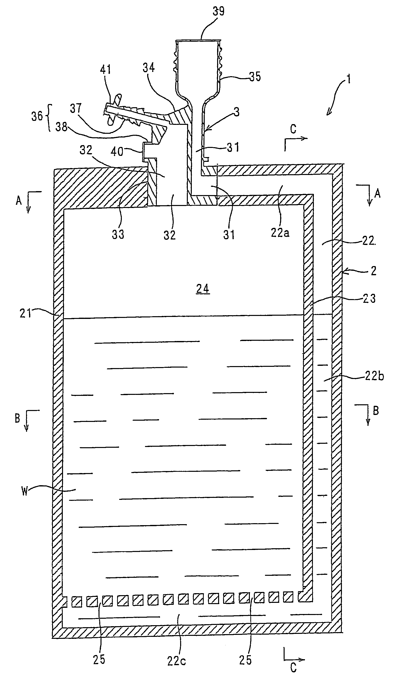
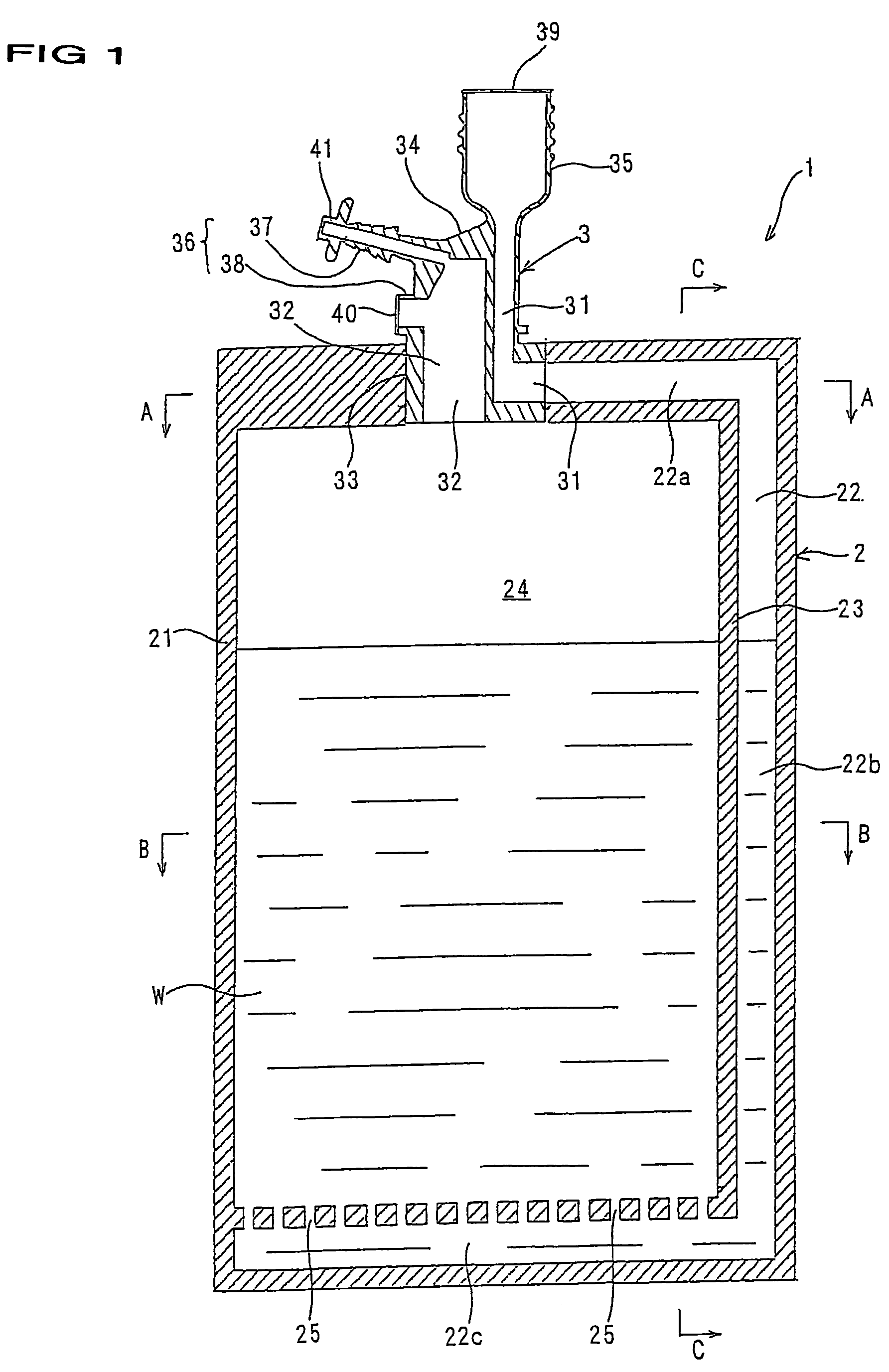
[0034]FIG. 1 is a longitudinal cross section of a liquid bag according to Embodiment 1 of the present invention; FIG. 2 is a longitudinal cross section of a mouth member according to Embodiment 1; FIG. 3 is a perspective diagram of a mouth member according to Embodiment 1 in a state that an opening and ports of the mouth member are opened; FIG. 4 is a cross section taken on line A—A of FIG. 1; FIG. 5 is a cross section taken on line B—B of FIG. 1; FIG. 6 is a cross section taken on line C—C of FIG. 1; FIG. 7 is a longitudinal cross section showing a use embodiment of the liquid bag as a humidifier; and FIG. 8 is a longitudinal cross section showing a use embodiment of the liquid bag as a nebulizer.

[0035]A liquid bag 1 mainly comprises: a bag main body 2 substantially like an envelop; water (sterilized, purified water) W contained in advance in the main bag body 2; and a mouth member 3 sealingly bonded to a part of a periphery of the bag main body 2.

[0036]The bag main body 2 is const...

use embodiment 1

[0048]Next, there will be given an example of a procedure in using the liquid bag 1 with the above construction as a humidifier.

[0049]First, with fingers placed on the pair of projections 41a, 41a of the blocking portion 41 illustrated in FIGS. 1 and 2, the neck portion 41b is twisted off to open the tube-connecting port 37 of the mouth member 3 (see: FIG. 3). As shown in FIG. 7, the tube-connecting port 37 is then inserted into and connected to one end of an elastic tube 51 whose other end is connected to an unillustrated oxygen mask to which oxygen is supplied. A connecting portion 52 is engaged with the first duct portion 35 of the mouth member 3 by means of the screw threads 35a provided on the first duct portion 35. At this time, a downwardly protruding portion of an oxygen introducing port 52a provided at the center of the connecting portion 52 pierces through the film 39 (see: FIG. 2), allowing communication between the oxygen introducing port 52a and the first flow path 31. ...

use embodiment 2

[0051]Next, there will be given an example of a procedure in using the liquid bag 1 with the above construction as a nebulizer (sprayer).

[0052]First, as shown in FIG. 8, the spray nozzle 61 is engaged with the first duct portion 35 of the mouth member 3 of the liquid bag 1 (liquid bag 1 in the state shown in FIG. 1) by means of the screw threads 35a provided on the first duct portion 35. At this time, a downwardly protruding portion of a liquid-introducing port 61a of the spray nozzle 61 pierces through the film 39 (see: FIG. 2), allowing communication between the liquid-introducing port 61a and the first flow path 31. The spray nozzle 61 comprises: a sucking portion 61b provided at an upper end of the liquid-introducing port 61a; a nozzle portion 61c provided above the sucking portion 61b for injecting oxygen; a guide portion 61d for guiding air to the outside together with oxygen containing water in a spray form; and a drain 61e for discharging droplets. The nozzle portion 61c of ...


PUM

PropertyMeasurementUnit
thickaaaaaaaaaa
timeaaaaaaaaaa
timeaaaaaaaaaa

Abstract

An object of the present invention is to provide a liquid bag that makes bubbling possible with a simple structure without increasing the number of parts.The liquid bag according to the present invention includes: a bag main body for containing a liquid, the bag main body constructed of a flexible thermoplastic resin sheet; and a mouth member constructed of a thermoplastic resin, the mouth member sealingly bonded to a part of a periphery of the bag main body. The mouth member has a sleeve-like seal portion sealingly bonded to the bag main body, the seal portion including a first flow path and a second flow path. The first flow path opens and extends along the periphery of the bag main body and the second flow path opens at a bottom surface of the seal portion to an inside of the bag main body.

Description

TECHNICAL FIELD[0001]The present invention relates to a liquid bag, a mouth member for the liquid bag and a production method thereof, and more particularly, to a liquid bag usable as a device for adding moisture (water vapor or water in spray form) to a gas such as air, oxygen, nitrogen, carbon dioxide or the like, and especially as a humidifier or nebulizer (sprayer) for oxygen.BACKGROUND ART[0002]Among conventional liquid bags comprising a bag main body constructed of a flexible thermoplastic resin sheet, known are liquid bags 1, 2 and 3 mentioned below.[0003]1. A liquid bag wherein a mouth member having one mouth portion is sealingly bonded to a part of the periphery of a bag main body shaped like an envelop.[0004]2. A liquid bag wherein a mouth member having two mouth portions is sealingly bonded to a part of the periphery of a bag main body shaped like an envelop (For example, Japanese Unexamined Patent Publication No. 2000-190997).[0005]3. A double-chamber liquid bag wherein ...

Claims


Application Information

Patent Timeline
Patent Type & Authority Patents(United States)
IPC IPC(8): B01F3/04A61M11/00B65D30/22A61M11/06A61M16/16B29C45/14B29L24/00B65D33/36
CPCA61M11/06A61M16/16A61M11/00B29C45/14
Inventor CHIBA, MITSURU
Owner SENKO MED INSTR MFG CO LTD
Why Eureka
Try Eureka