Gear grinding machine

a grinding machine and gear technology, applied in the direction of gear teeth, gear-teeth manufacturing apparatus, abrasive surface conditioning devices, etc., can solve the problems of poor accuracy, reduced sharpness, wear of the grinding wheel,

Active Publication Date: 2007-04-03
MITSUBISHI HEAVY IND MACHINE TOOL CO LTD
View PDF7 Cites 26 Cited by
  • Summary
  • Abstract
  • Description
  • Claims
  • Application Information

AI Technical Summary

Problems solved by technology

As grinding proceeds, the threaded grinding wheel wears, and its sharpness decreases.
The necessity for the operator's manual work for turning the rotary dressing device (dressing tool) in order to modify the wheel pressure angle, however, may result in poor accuracy.
Moreover, a gear grinding machine of the type, which cannot turn the rotary dressing device, has hitherto been unable to modify the wheel pressure angle.

Method used


Image

  • Gear grinding machine
  • Gear grinding machine
  • Gear grinding machine

Examples


embodiment 1

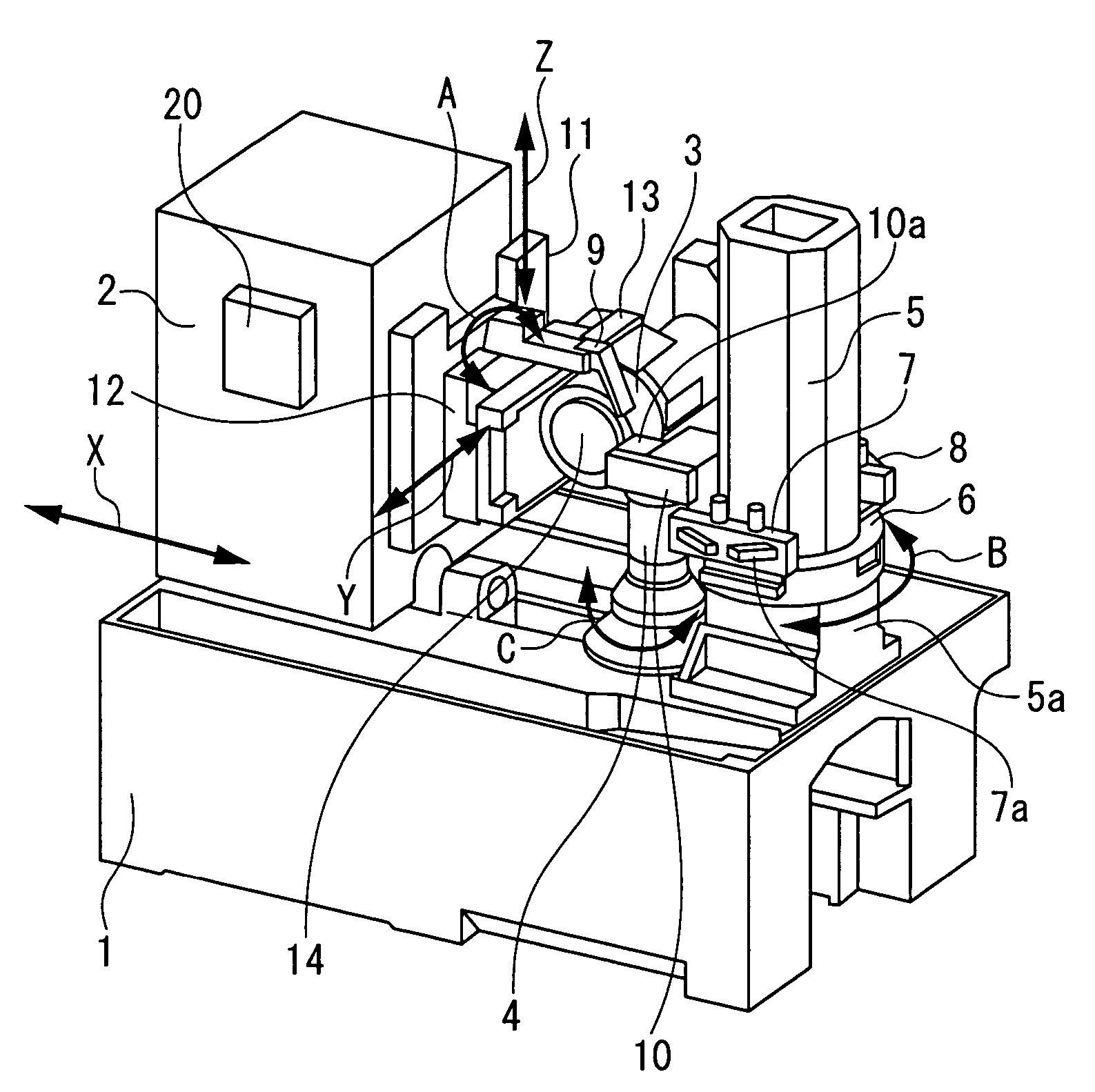
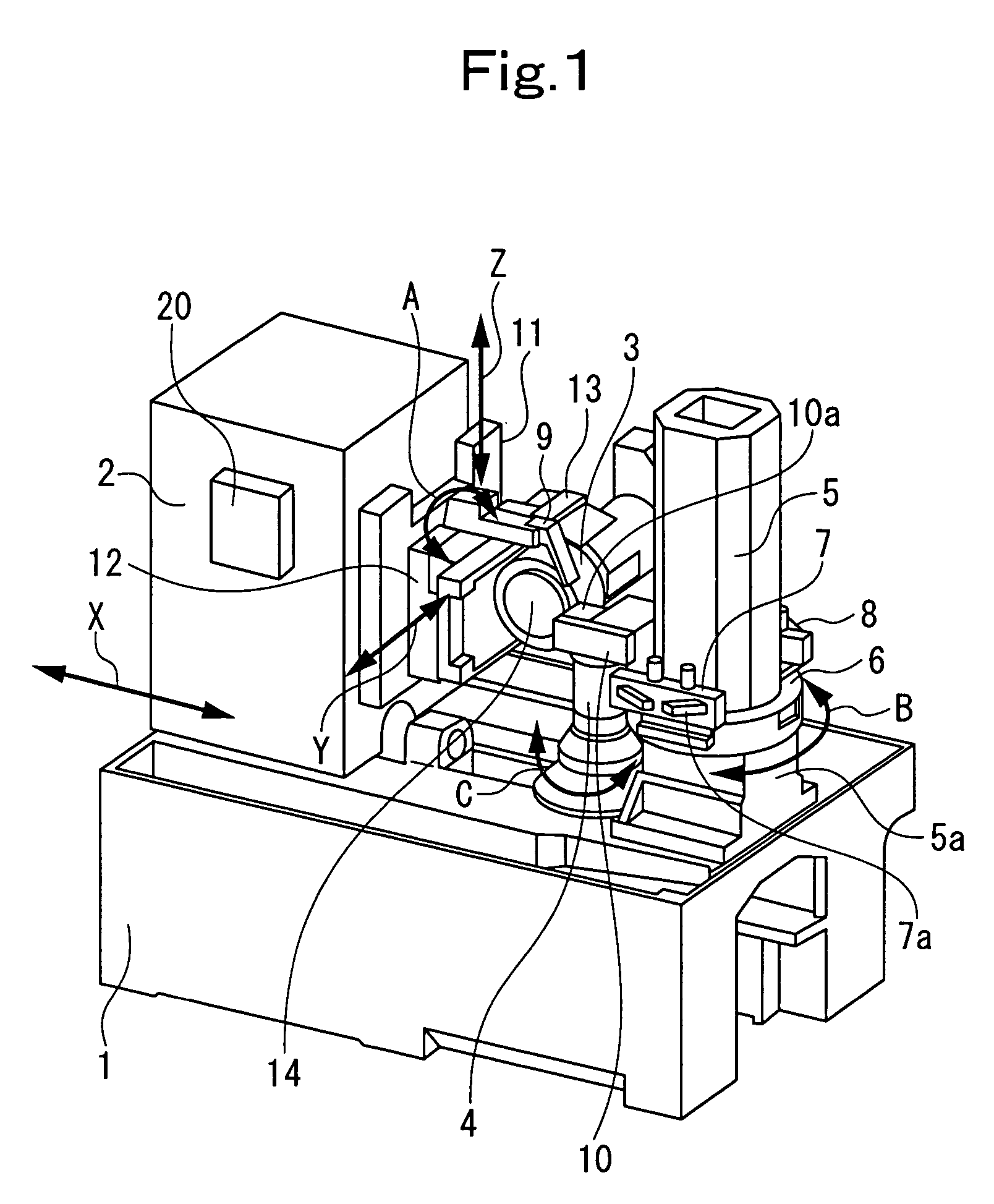
[0066]Embodiment 1 of the present invention applied to the gear grinding machine shown in FIGS. 1 to 5(a), 5(b) will be described with reference to FIGS. 6(a) to 6(c).

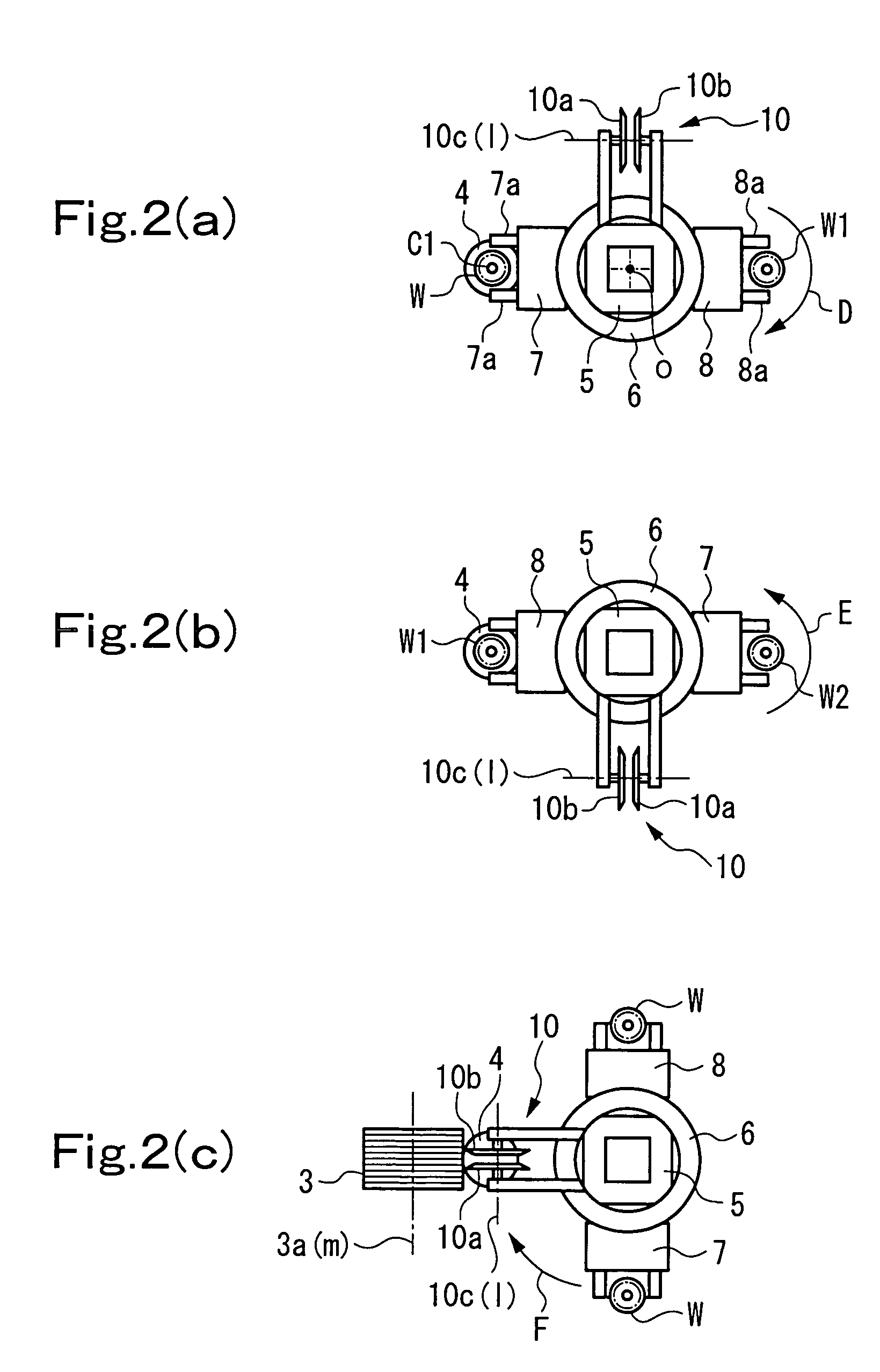
[0067]In performing ordinary dressing, a line connecting the center O1 of the threaded grinding wheel 3 (the central point of the grinding wheel axis 3a(m)) and the center O2 of the dressing tools 10a, 10b (the central point of the dresser axis 10c(l)) is rendered horizontal, as shown in FIG. 6(a). At this time, a center distance, which is the distance between the centers O1 and O2, is D.

[0068]To change the wheel pressure angle of the threaded grinding wheel 3, the positions of the dressing tools 10a, 10b are fixed at the same positions as in FIG. 6(a), and the center distance as the distance between the centers O1 and O2 is kept to be D (namely, the dressing tools 10a, 10b are kept in contact with the flanks of the threads of the threaded grinding wheel 3). Under these conditions, the position in the X-direction and t...

embodiment 2

[0081]In Embodiment 1, the increase (decrease) in the wheel pressure angle (numerical value) at the right flank RF and the decrease (increase) in the wheel pressure angle (numerical value) at the left flank LF are rendered equal. In Embodiment 2, on the other hand, the increase and decrease in the wheel pressure angles (numerical values) at the right and left flanks are rendered different.

[0082]In Embodiment 1, therefore, the distance over which the threaded grinding wheel 3 is continuously moved in the Y-direction (moving distance in the Y-direction per rotation) during dressing is equated with the lead of the threads formed in the threaded grinding wheel 3. In Embodiment 2, by contrast, the distance over which the threaded grinding wheel 3 is continuously moved in the Y-direction (moving distance in the Y-direction per rotation) during dressing is rendered slightly longer or shorter than the lead of the threads formed in the threaded grinding wheel 3.

[0083]As has been well known t...


PUM

PropertyMeasurementUnit
pressure angleaaaaaaaaaa
wheel pressure angleaaaaaaaaaa
rotational speedaaaaaaaaaa

Abstract

A gear grinding machine comprises: a moving mechanism rotatably mounted with a threaded grinding wheel, and arranged to move the threaded grinding wheel along directions of X, Z, and Y, and to turn the threaded grinding wheel in a Y-Z plane; an NC device for controlling the position of the threaded grinding wheel; and a rotary dressing device having a dressing tool which contacts the flanks of the threads of the threaded grinding wheel, while rotationally driven, to perform dressing. The NC device numerically controls the moving mechanism so as to adjust the positions in the directions of X and Z, and the turning position in the Y-Z plane of the threaded grinding wheel, while keeping contact of the dressing tool with the flanks of the threads of the threaded grinding wheel, in order to modify the wheel pressure angle of the threaded grinding wheel.

Description

BACKGROUND OF THE INVENTION[0001]1. Field of the Invention[0002]This invention relates to a gear grinding machine arranged to perform grinding using a threaded grinding wheel, and equipped with a rotary dressing device. The gear grinding machine can modify the wheel pressure angle of the threaded grinding wheel with high accuracy by use of numerical control.[0003]2. Description of the Related Art[0004]A gear grinding machine, in which a gear-shaped workpiece after heat treatment is ground by “a threaded grinding wheel,” a gear grinding tool, to finish a gear, has so far been known. The threaded grinding wheel is an annular grinding wheel having threads (rack teeth) formed spirally on its outer peripheral surface. Grinding is performed, with the positions in an orthogonal coordinate system (positions on the X-axis, Y-axis and Z-axis) of the threaded grinding wheel, and the rotational speed of the threaded grinding wheel being numerically controlled.[0005]As grinding proceeds, the thr...

Claims


Application Information

Patent Timeline
Patent Type & Authority Patents(United States)
IPC IPC(8): B24B1/00B23F19/05B24B53/075
CPCB23F23/1225B24B53/085B23F1/02
Inventor YANASE, YOSHIKOTOMASUO, KOICHI
Owner MITSUBISHI HEAVY IND MACHINE TOOL CO LTD
Why Eureka
Try Eureka