Handle assembly having an integral slider therefor and electrical switching apparatus employing the same

Inactive Publication Date: 2007-04-03
EATON CORP
View PDF7 Cites 12 Cited by
  • Summary
  • Abstract
  • Description
  • Claims
  • Application Information

AI Technical Summary

Benefits of technology

[0019]The base member and the handle member coupled thereto may be movable among ON and OFF positions within the opening of the housing assembly wherein each of the first and second integral resilient legs is arcuate shaped and structured to extend generally outwardly from the base member in order that the opening is substantially closed regardless of the position of the handle assembly with respect to the housing assembly. Each of the first and second integral resilient legs may include an end portion, a thickness and an undercut between the second end of the handle member and the end portion, in order to reduce the thickness at the location of the undercut thereby increasing the resiliency of the first and second integral resilient legs. The undercuts may be grooves.

Problems solved by technology

Thus, while the conventional components of a telecommunication system circuit breaker may not be unique, the necessity of having a reduced size requires specialized configurations and robust components that are different than power distribution circuit breakers.
This is especially true where the telecommunication system circuit breakers are used in environments wherein the circuit breaker may be expected to operate for over 10,000 operating cycles and 50 tripping cycles; however, the reduced size telecommunication system circuit breakers are typically limited to a current rating of 30 amps.
In smaller circuit breakers which have a low trip force, the use of a common trip bar is not feasible.
Such designs require two or more separately made parts (e.g., without limitation, the slider, and the handle member) and, to ensure proper and sufficient engagement between such separate parts, a complex interface geometry is required which adds to the cost of the handle assembly.

Method used


Image

  • Handle assembly having an integral slider therefor and electrical switching apparatus employing the same
  • Handle assembly having an integral slider therefor and electrical switching apparatus employing the same
  • Handle assembly having an integral slider therefor and electrical switching apparatus employing the same

Examples


Embodiment Construction

[0044]As used herein, directional terms, such as “vertical,”“horizontal,”“left,”“right”, “clockwise,” etc. relate to the circuit breaker 10 as shown in most of the Figures, that is, with the handle assembly 400 located at the left side of the circuit breaker 10 (FIG. 5), and are not limiting upon the claims.

[0045]The present invention is disclosed in association with a telecommunication system circuit breaker 10, although the invention is applicable to a wide range of circuit breakers for a wide range of applications such as but not limited to residential or molded case circuit breakers.

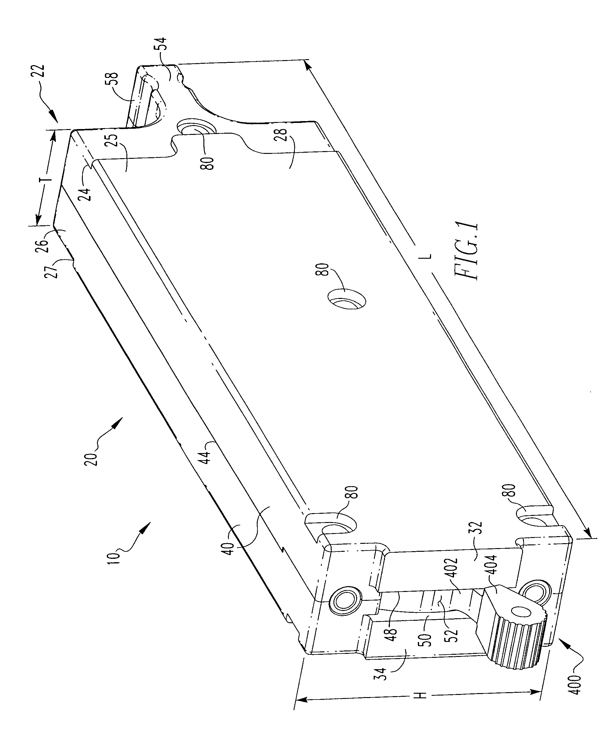
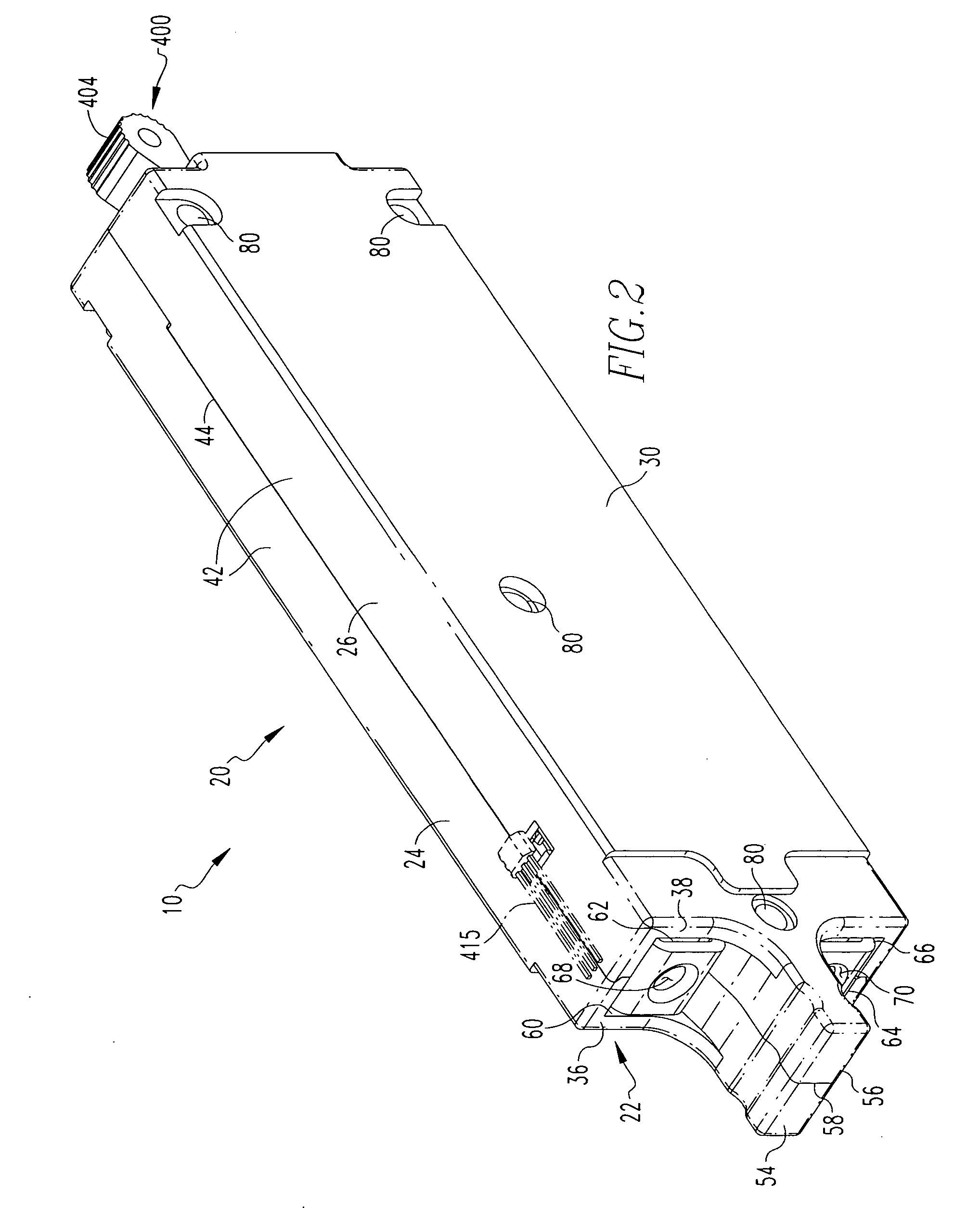
[0046]As shown in FIGS. 1–4, a circuit breaker 10 includes a housing assembly 20, a current path assembly 100 (FIG. 3), an operating mechanism 200, a trip device 300, and a handle assembly 400. Generally, the current path assembly 100 includes a pair of separable contacts 105 (FIG. 3) including a first, fixed contact 110 and a second, movable contact 120. The movable contact 120 is structured to be m...


PUM


Abstract

A handle assembly is provided for a circuit breaker which includes a housing assembly that defines a substantially enclosed space housing an operating mechanism. The handle assembly is preferably a single-piece and includes a base member which is coupled to the operating mechanism, and a handle member having a first end which protrudes from an opening of the housing assembly, and a second end coupled to the base member. The base member includes first and second integral resilient legs which are disposed within the opening and are supported by posts protruding from the housing assembly, in order to resist undesired access into the substantially enclosed space therein. The first and second integral resilient legs each include a groove which increases the resiliency of the leg. The handle assembly is preferably symmetric about the longitudinal axis of the handle member.

Description

CROSS-REFERENCE TO RELATED APPLICATIONS[0001]U.S. patent application Ser. No. 11 / 254,529, filed Oct. 19, 2005, entitled “CIRCUIT BREAKER INCLUDING LINE CONDUCTOR HAVING BEND PORTION TO INCREASE CONTACT GAP”;[0002]U.S. patent application Ser. No. 11 / 254,300, filed Oct. 19, 2005, entitled “CIRCUIT BREAKER INTERMEDIATE LATCH”;[0003]U.S. patent application Ser. No. 11 / 254,298, filed Oct. 19, 2005, entitled “ELECTRICAL SWITCHING APPARATUS INCLUDING OPERATING MECHANISM HAVING INSULATING PORTION”;[0004]U.S. patent application Ser. No. 11 / 254,514, filed Oct. 19, 2005, entitled “AUXILIARY SWITCH INCLUDING MOVABLE SLIDER MEMBER AND ELECTRIC POWER APPARATUS EMPLOYING SAME”;[0005]U.S. patent application Ser. No. 11 / 254,299, filed Oct. 19, 2005, entitled “CONTACT ARM WITH 90 DEGREE OFFSET”;[0006]U.S. patent application Ser. No. 11 / 254,535 filed Oct. 19, 2005, entitled “CIRCUIT BREAKER COMMON TRIP LEVER”;[0007]U.S. patent application Ser. No. 11 / 254,509 filed Oct. 19, 2005, entitled “CIRCUIT BREA...

Claims


Application Information

Patent Timeline
IPC IPC(8): H01H3/20
CPCH01H71/0214H01H71/521H01H2071/046H01H71/52
Inventor RODGERS, CRAIG A.BRAND, RONALD W.
Owner EATON CORP
Why Eureka
Try Eureka