
Low threshold level radiation detector

a radiation detector and low threshold technology, applied in the direction of radiation measurement, instruments, measurement devices, etc., can solve the problems of inability to detect electrical signals, inability to accurately measure radiation, and inability to provide detectable electrical signals, etc., to achieve more accurate readings, reduce the detection threshold, and improve the effect of detection accuracy

Active Publication Date: 2007-04-03
NEC LCD TECH CORP +1
View PDF4 Cites 14 Cited by
  • Summary
  • Abstract
  • Description
  • Claims
  • Application Information

AI Technical Summary

Benefits of technology

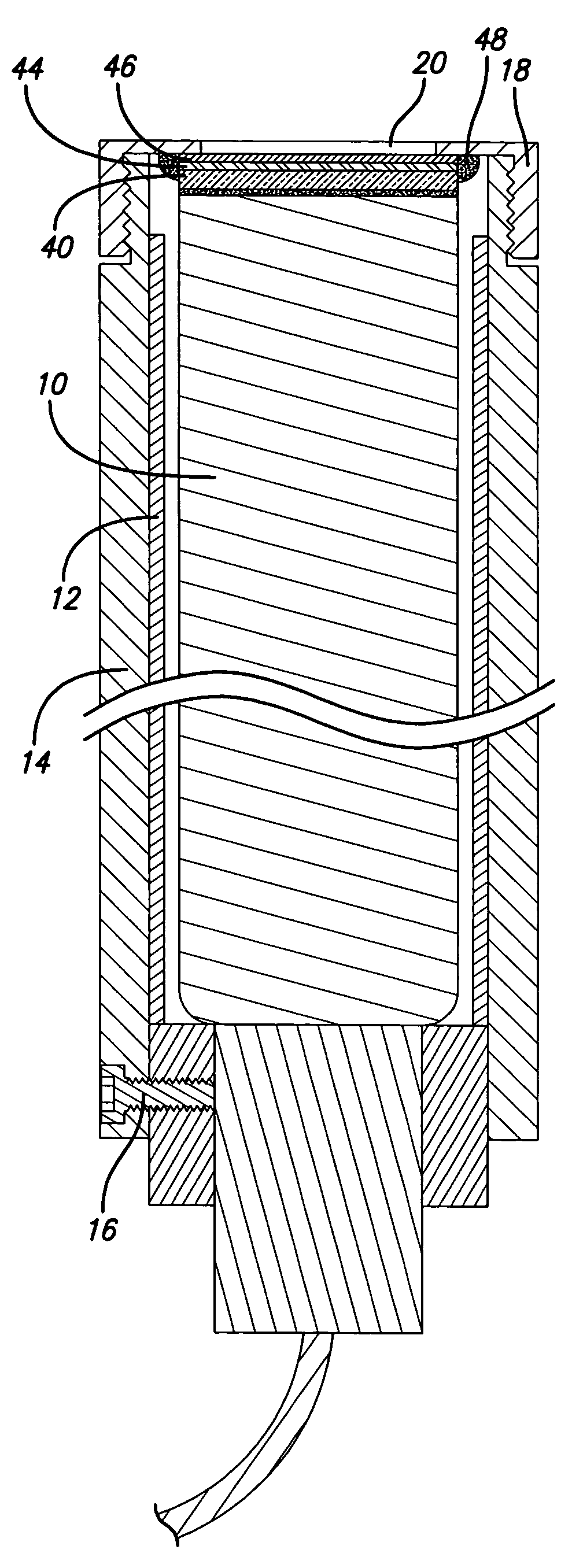
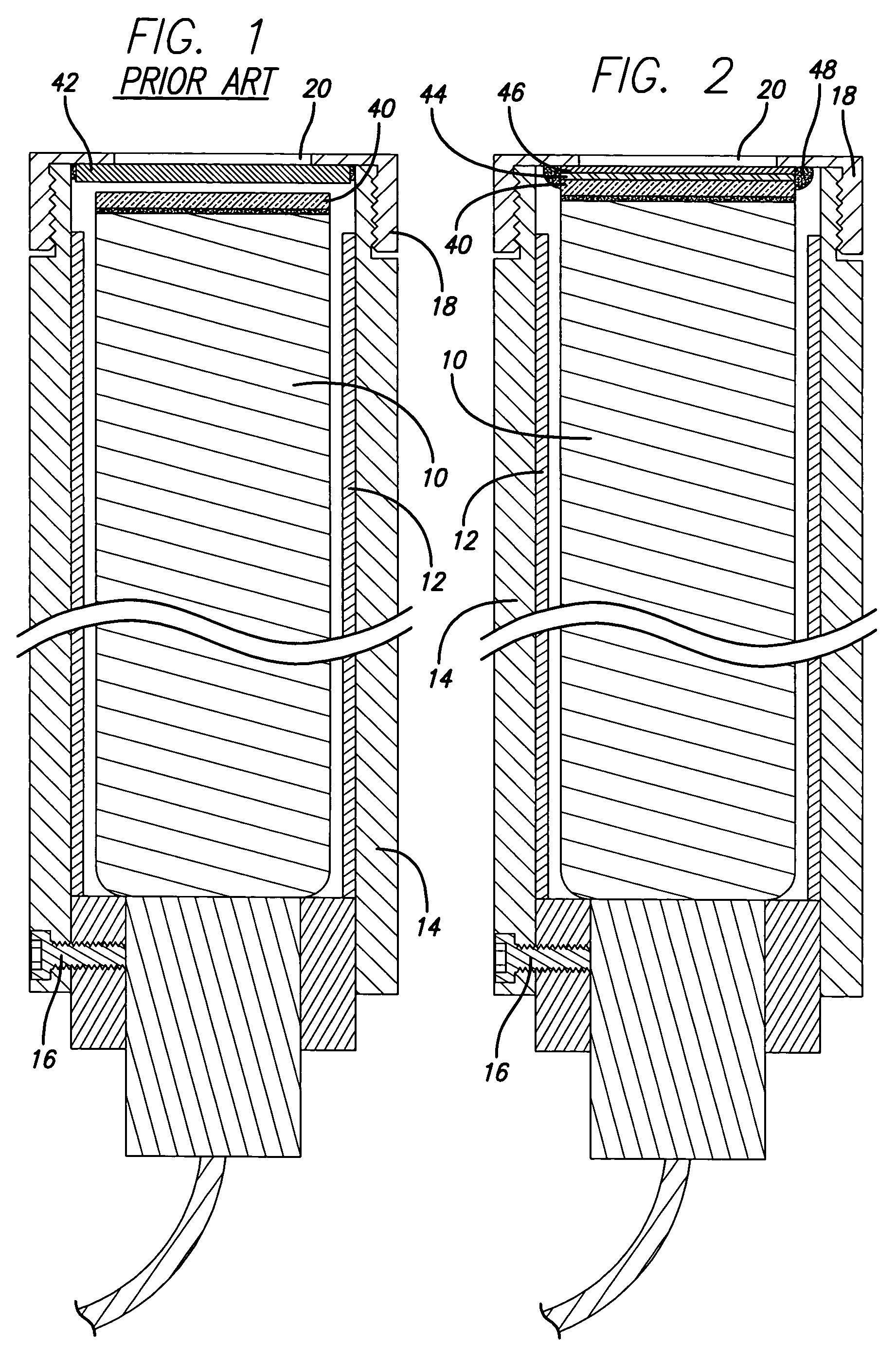
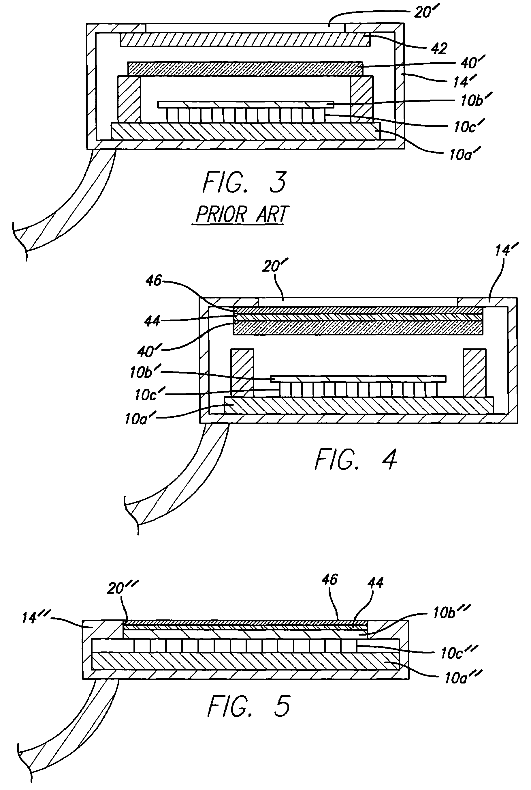
[0008]The present invention is directed to a low threshold level radiation detector in which reflective material is directly applied to a radiation detector surface without a separate window cover to allow detection of low levels of radiation. The present invention, therefore, is an improvement on existing radiation detectors because it allows a lower detectable threshold and more accurate readings. The radiation detector of the present invention, therefore, is capable of measuring lower energy or lower levels of radiation more accurately than known radiation detectors.

Problems solved by technology

The number of photoelectrons produced will be comparable to the number of incident light photons and thus, the charge on the photoelectrons will be too small to provide a detectable electrical signal.
First, the window cover blocks ambient light from entering the radiation detector.
Ambient light could cause errors in the measured radiation.
The external light may also cause temporary / permanent damage to sensitive components.
Second, the window cover focuses scintillated light into the measuring device.
Third, the window cover protects sensitive components from damaging agents such as gasses and solids in the measured medium.
Due to the window cover's thickness, however, the window cover also attenuates a portion of the radiation being measured (e.g. low energy radiation) in that the energy cannot penetrate the window cover.
In other words, the attenuation caused by the thickness of the window cover can introduce significant errors in results produced by the radiation detection devices.
Accurate detection of radiation is critical and erroneous results can be dangerous.

Method used


Image

  • Low threshold level radiation detector
  • Low threshold level radiation detector
  • Low threshold level radiation detector

Examples


Embodiment Construction

[0018]The present invention is directed to a low threshold level radiation detector in which a thin layer of protective covering is directly applied to a radiation detector surface without a window cover to allow detection of low levels of radiation. The present invention improves existing radiation detectors by allowing a lower detectable threshold and readings that are more accurate. The attenuation of low-level radiation by structural window cover material used in typical radiation detectors is reduced when the window cover is not present. The radiation detector of the present invention, therefore, is capable of measuring lower energy or lower levels of radiation more accurately than known radiation detectors.

[0019]As mentioned, current radiation detectors use structural material or window covers to cover radiation detector components. The window cover serves three necessary purposes: blocking ambient light from entering the radiation detector, focusing scintillated light into th...


PUM


Abstract

A radiation detector of the present invention has at least one radiation measuring component and a radiation detector surface. A layer of protective covering substantially covers the radiation detector surface and protects the at least one radiation measuring component. The layer of protective covering preferably includes a protective material sub-layer and may include an optional coating sub-layer. The radiation detector surface may be, for example, a scintillator, cover glass, or chip surface.

Description

[0001]The present application is an application claiming the benefit under 35 USC Section 119(e) of U.S. Provisional Patent Application Ser. No. 60 / 488,079, filed Jul. 16, 2003. The present application is based on and claims priority from this application, the disclosure of which is hereby expressly incorporated herein by reference.BACKGROUND OF INVENTION[0002]The present invention is directed to a low threshold level radiation detector in which reflective material is directly applied to a radiation detector surface without a separate window cover to allow detection of low levels of radiation.[0003]Radiation detection devices or radiation detectors typically use a window cover such as an aluminum window or an aluminized MYLAR® polyester film window (MYLAR® is a biaxially oriented, thermoplastic film made from ethylene glycol and dimethyl terephthalate (DMT)) to cover the radiation detector components such as Photomultiplier Tubes (PMTs), Geiger-Mueller Tubes (GMTs), or Solid State D...

Claims


Application Information

Patent Timeline
Patent Type & Authority Patents(United States)
IPC IPC(8): G01T1/20
CPCG01T1/2002
Inventor HEVERLY, MATTHEW
Owner NEC LCD TECH CORP
Learn More