Integrated circuit and optical pickup device

a pickup device and integrated circuit technology, applied in the field of integrated circuits, can solve the problems of circuit operation destabilization, coupling noise generation, weak current obtained by conversion through the light-receiving element, etc., and achieve the effect of stabilizing circuit operation and reducing coupling nois

Inactive Publication Date: 2007-04-03
SHARP KK
View PDF5 Cites 3 Cited by
  • Summary
  • Abstract
  • Description
  • Claims
  • Application Information

AI Technical Summary

Benefits of technology

[0017]The present invention was made in light of the foregoing problem. An object of the present invention is therefore to provide an integrated circuit capable of reducing a coupling noise generated in a first-stage amplifier circuit among a plurality of serially connected amplifier circuits (amplifiers), thereby stabilizing circuit operation of a following-stage amplifier.
[0019]According to this arrangement, the noise reducing means reduces the noise generated in the first-stage amplifier, thereby preventing the noise from being supplied to a following-stage amplifier through the common power source, which is shared by the first-stage amplifier and the other amplifiers.
[0020]As a result, operation of the integrated circuit as a whole is stabilized, because the noise generated in the first-stage amplifier, e.g. the coupling noise, does not destabilize operation of the following-stage amplifier.
[0022]If the noise reducing means is the integrator including a resistor and a capacitor, it is easy to incorporate the noise reducing means into the integrated circuit.
[0023]In addition, because the integrator includes the resistor and the capacitor, the integrator can be formed easily by using existing elements.

Problems solved by technology

In general, the current obtained by conversion through the light-receiving element is very weak.
As a result, circuit operation is destabilized.
The coupling noise is generated for various reasons.
A salient reason is that a metal layer and an insulating layer, which are laminated in the integrated circuit, are not jointed properly.
In this case, if there is a defective portion where a metal layer and an insulating layer are not jointed properly, the defective portion generates a noise (hereinafter “junction noise”).
The rapid voltage fluctuation at the output terminal further generates the coupling noise, thereby creating a vicious circle.

Method used


Image

  • Integrated circuit and optical pickup device
  • Integrated circuit and optical pickup device
  • Integrated circuit and optical pickup device

Examples


Embodiment Construction

[0034]The following describes one embodiment of the present invention. In the present embodiment, described as one example of the integrated circuit of the present invention is a light-receiving amplifier element provided to an optical pickup device.

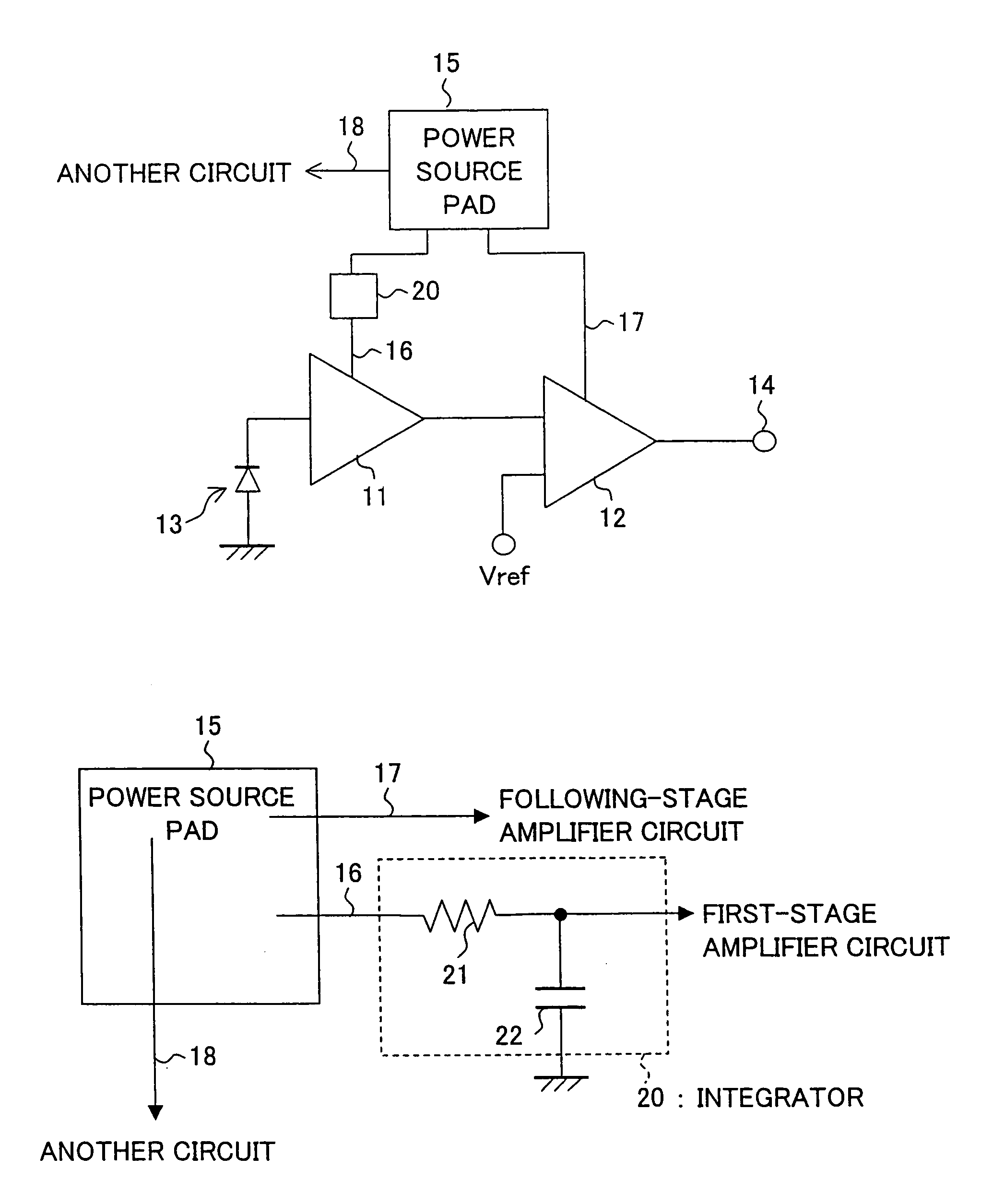
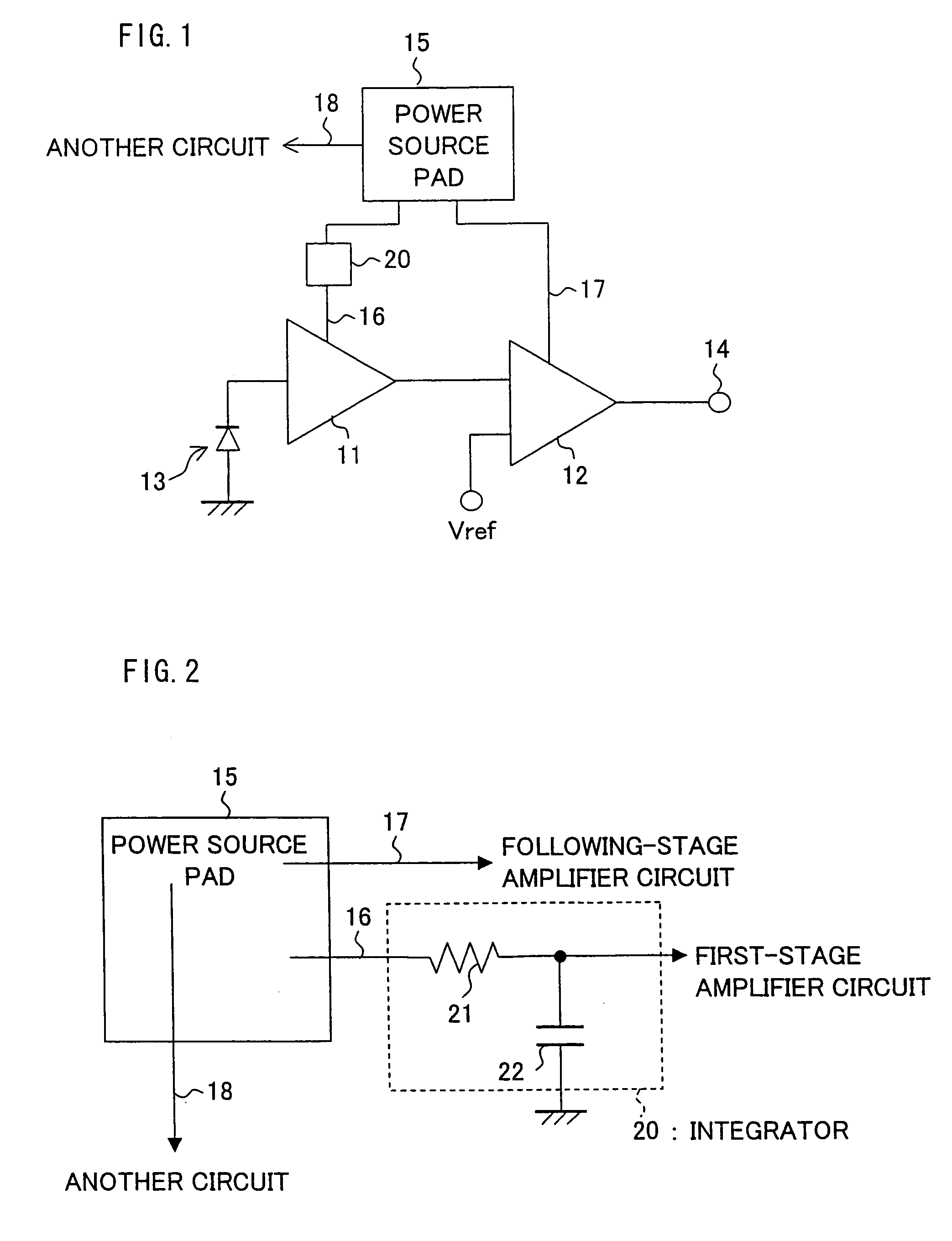
[0035]FIG. 1 is a schematic block diagram illustrating the light-receiving amplifier element of the present embodiment.

[0036]As shown in FIG. 1, the light-receiving amplifier element of the present embodiment includes a first-stage amplifier circuit 11, a following-stage amplifier circuit 12, and a light-receiving element 13. The following-stage amplifier circuit 12 is connected to an output side of the first-stage amplifier circuit 11. The light-receiving element 13 is connected to an input side of the first-stage amplifier circuit 11. The first-stage amplifier circuit 11 and the following-stage amplifier circuit 12 are connected in series. An electrical signal generated by conversion through the light-receiving element 13 is amplified ...


PUM


Abstract

An integrated circuit includes a first-stage amplifier circuit and a following-stage amplifier circuit connected in series, a common power source pad for supplying power to the amplifier circuits, and metal wires respectively connecting the common power source pad to the amplifier circuits. On the metal wire which connects the first-stage amplifier and the power source pad, an integrator is electrically connected. This arrangement decreases a coupling noise generated in the first-stage amplifier circuit, thereby stabilizing circuit operation of the following-stage amplifier circuit.

Description

[0001]This nonprovisional application claims priority under 35 U.S.C. § 119(a) on Patent Application No. 2003 / 328527 filed in Japan on Sep. 19, 2003, and Patent Application No. 2004 / 184184 filed in Japan on Jun. 22, 2004. The entire contents of these applications are hereby incorporated by reference.FIELD OF THE INVENTION[0002]The present invention relates to an integrated circuit including a plurality of amplifiers connected in series. The present invention is particularly suitable for an optical pickup device including an integrated circuit which includes (i) a plurality of amplifiers for sequentially increasing gain and (ii) a circuit having large gain, and more suitable for an integrated circuit which especially requires a high-frequency characteristic.BACKGROUND OF THE INVENTION[0003]Optical discs are widely used as mediums for recording sounds, videos, document data, and the like. There have been developed various kinds of devices for recording or reproducing information to or...

Claims


Application Information

Patent Timeline
Patent Type & Authority Patents(United States)
IPC IPC(8): H03F3/04H03F3/08H03F1/26H03F3/68
CPCH03F1/26H03F3/087H03F3/68
Inventor KISHIDA, TOMOTAKE
Owner SHARP KK
Why Eureka
Try Eureka