

Apparatus for estimating quantity of intake air for internal combustion engine
- Summary
- Abstract
- Description
- Claims
- Application Information
AI Technical Summary
Benefits of technology
Problems solved by technology
Method used
Image

Examples
first embodiment
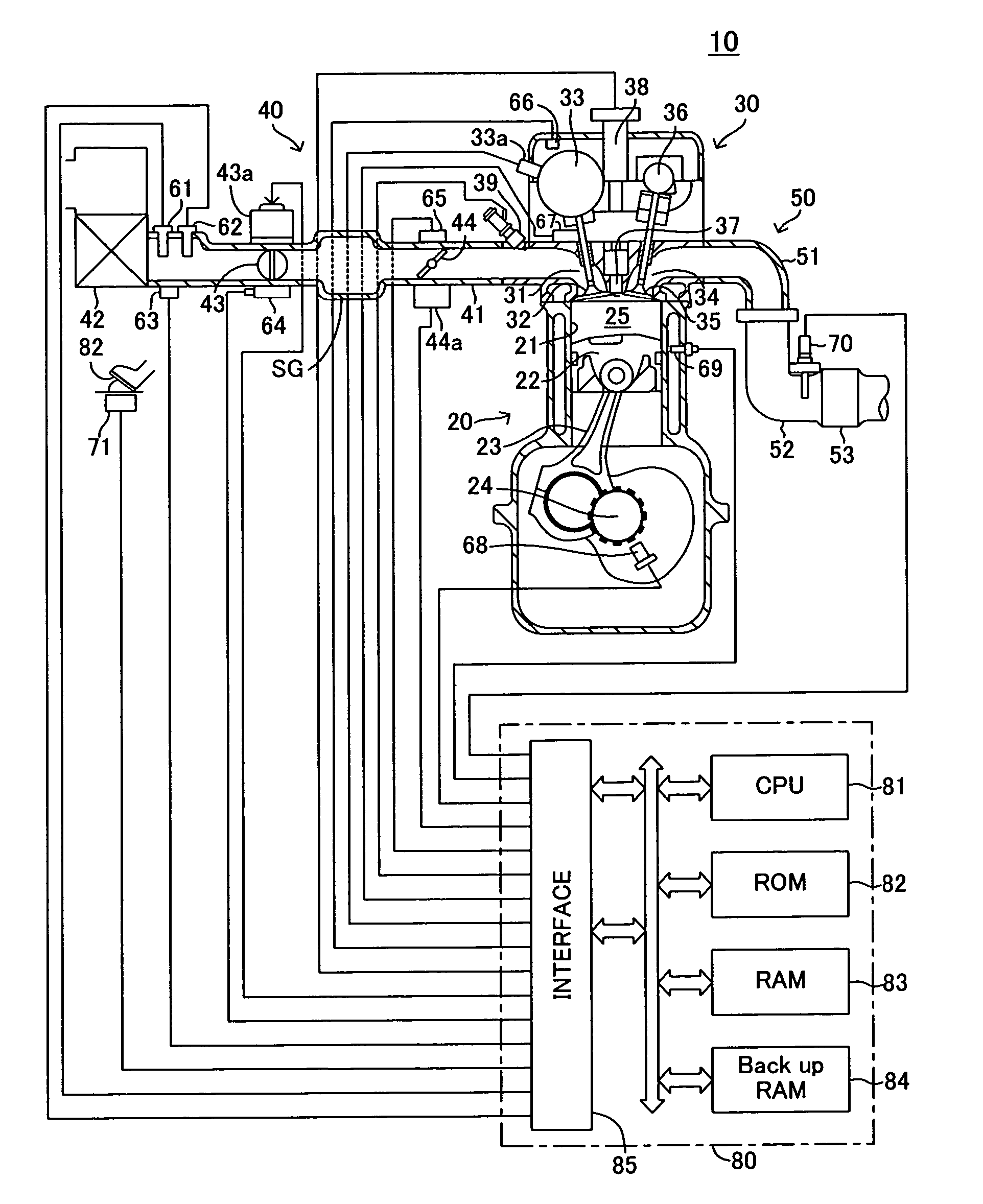
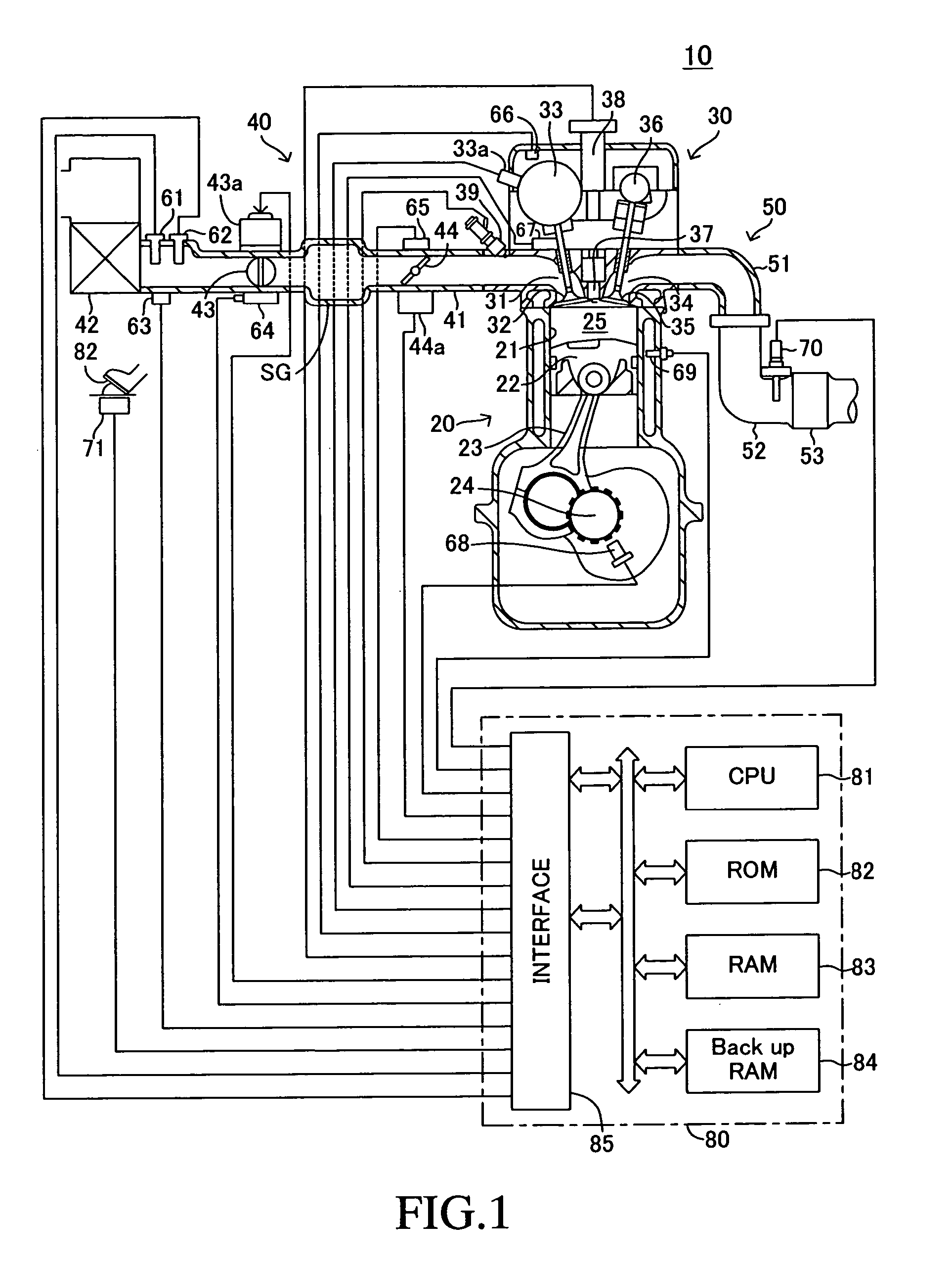
[0050]Embodiments of a fuel injection quantity control apparatus including an intake-air quantity estimation apparatus for an internal combustion engine according to the present invention will be described with reference to the drawings. FIG. 1 shows a schematic configuration of a system configured such that a fuel injection quantity control apparatus according to the present invention is applied to a spark-ignition multi-cylinder (e.g., 4-cylinder) internal combustion engine 10.
[0051]The internal combustion engine 10 includes a cylinder block section 20 including a cylinder block, a cylinder block lower-case, an oil pan, etc.; a cylinder head section 30 fixed on the cylinder block section 20; an intake system 40 for supplying gasoline-air mixture to the cylinder block section 20; and an exhaust system 50 for emitting exhaust gas from the cylinder block section 20 to the exterior of the engine.
[0052]The cylinder block section 20 includes cylinders 21, pistons 22, connecting rods 23,...
second embodiment
[0190]As described above, the intake-air quantity estimation apparatus according to the present invention includes the throttle-model correction section, which corrects a value (flow coefficient) to be used in the calculation equation of the throttle model M2, through utilization of the fact that, when the internal combustion engine 10 is in the steady state of operation, “the intake-air flow rate mtAFM measured by the air flowmeter 61, which serves as an intake-air-flow-rate-measuring means” and “the cylinder intake-air flow rate mc obtained by the intake valve model M4” become equal to each other.
[0191]In other words, the throttle-model correction section (intake-pipe-air-pressure reverse model M110) obtains the intake-pipe air pressure Pm to be used in the throttle model M2, through utilization of the fact that the intake-air flow rate mtAFM obtained on the basis of an output from the air flowmeter 61 and the cylinder intake-air flow rate mc obtained by the intake valve model M4 ...
PUM
 Abstract
Description
Claims
Application Information