Automated bill payment system

a bill payment and automatic technology, applied in the field of financial transaction system and method, can solve the problems of paper cheque processing, significant cost to the payees who receive and handle the client's cheque, and inability to avoid mailing a hard copy of the bill, so as to facilitate payment and facilitate client operation

Inactive Publication Date: 2007-04-03
TELPAY
View PDF14 Cites 193 Cited by
  • Summary
  • Abstract
  • Description
  • Claims
  • Application Information

AI Technical Summary

Benefits of technology

[0011]The present invention serves to overcome the deficiencies of the prior art by providing a fully automated and secure bill payment system which is extremely simple for clients to operate and which allows the biller's the opportunity to use the billing process as a marketing tool. A processing web site is established which interconnects via the Internet to a plurality of financial institutions and billers. Each biller has an established web site into which a client of the biller can enter and view a bill image using a personal computer or similar device connected to the Internet. The bill image is actually part of a HTML form which contains hidden identifying information of the biller. To facilitate payment, the client selec

Problems solved by technology

The process described above is paper intensive and administratively burdensome, not to mention the fact it often required to be done for multiple billers at least monthly.
Paper cheque processing also entails significant costs to the payees who receive and handle the client's cheques.
Further, the mailing of a hard copy of the bill is not avoided, nor is the handling of a remittance slip by the bank.
Additionally, the service is restricted to client's of a particular financial institution offering such a bill payment service.
However, it does not completely eliminate the generation of hard copies of bills from merchants or the p

Method used


Image

  • Automated bill payment system
  • Automated bill payment system
  • Automated bill payment system

Examples


Embodiment Construction

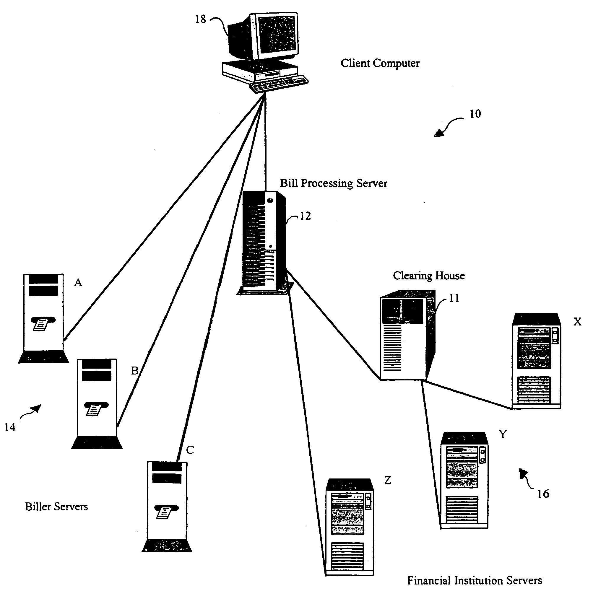
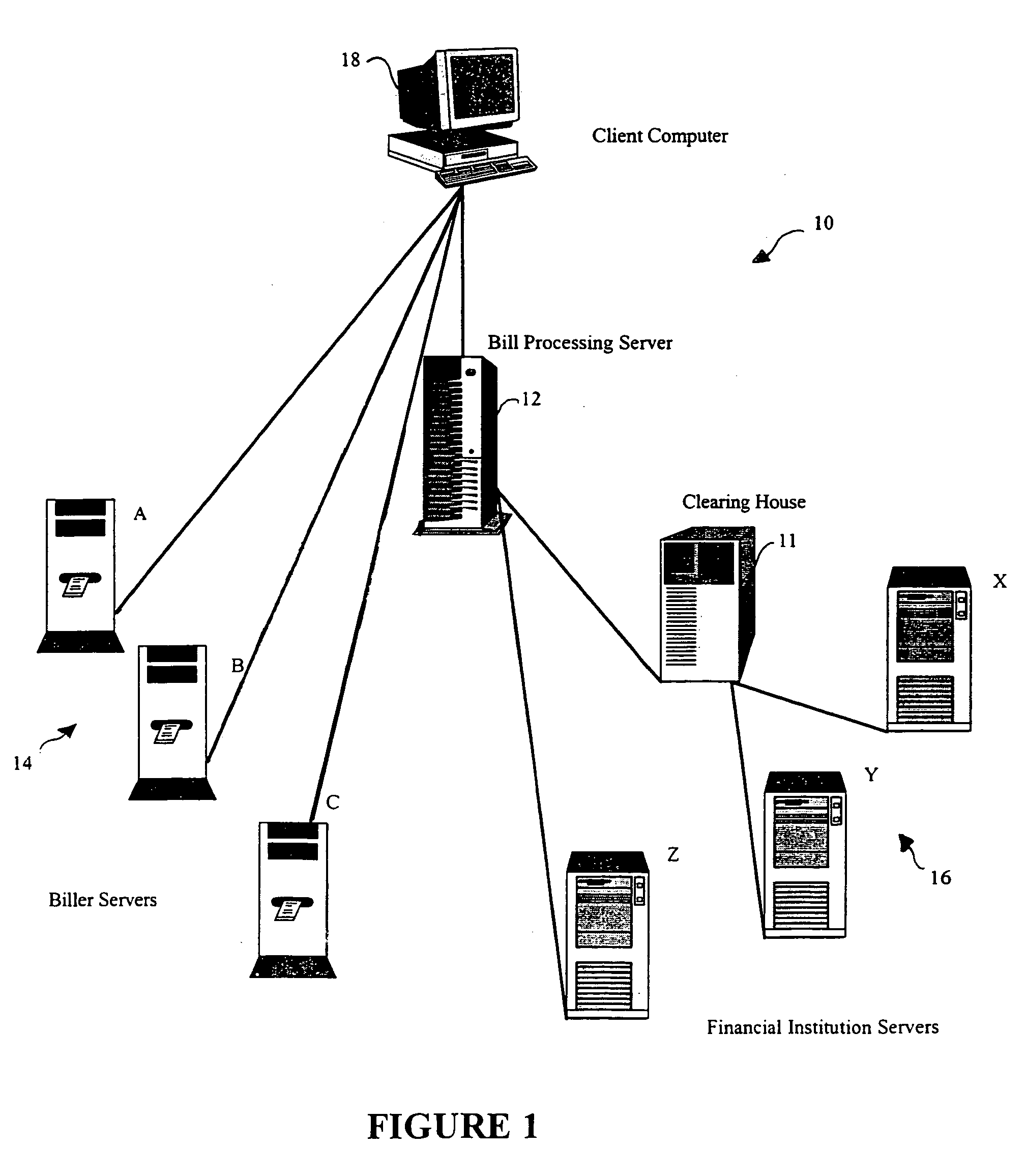
[0030]Referring to FIG. 1, a network diagram depicting the system of the present invention is presented. A network (generally depicted at 10) interconnects clearing house 11, bill processing server 12, biller servers A, B and C (generally depicted as 14), financial institution servers X, Y and Z (generally depicted as 16) and client computer 18. For the sake of simplicity, the network components (e.g routers, switches, etc.) have not been shown nor has all of the connectivity between the components integral to the system of the present invention (e.g. client computer 18 connects to each biller server).

[0031]In the preferred embodiment network 10 is the Internet. The Internet, is a worldwide system of computer networks—a network of networks in which users at any one computer can, if they have permission, get information from any other computer. The Internet is a public, cooperative, and self-sustaining information system accessible to hundreds of millions of people worldwide. Physica...


PUM


Abstract

The present invention provides a fully automated and secure bill payment system which is extremely simple for clients to operate. A processing web site is established which interconnects via the Internet to a plurality of financial institutions, billers and clients. Each biller has an established web site into which a client of the biller can enter and view a bill image using a personal computer or similar device connected to the Internet. The bill image is actually part of a HTML form which contains hidden identifying information of the biller. To facilitate payment, the client selects a bill payment icon presented graphically within the body of the bill image. This action initiates a sequence of events, including the forwarding of the HTML form to the processing web site, a confirmation message being sent to the client, confirmation by the client, and the debiting and crediting of client and biller accounts respectively. Instead of requiring the client to log into the biller's web site, the bill can also be presented to the client by way of an e-mail message. Similar to the previous scenario, bill payment is accomplished by the client selecting a bill payment icon.

Description

BACKGROUND TO THE INVENTION[0001]1. Field of Invention[0002]This invention relates generally to a financial transaction system and method, and more particularly to a computerized bill payment system for use in a wire or wireless network which requires a minimal amount of user interaction to affect bill payment.[0003]2. Description of the Related Prior Art[0004]In its crudest form, the bill payment transaction cycle includes the following steps: (a) generation of a bill by a biller; (b) mailing the bill to the client; (c) client writing a cheque for the invoiced amount and mailing the cheque along with a remittance slip to the biller; (d) biller manually depositing cheque in their bank account; (e) when cheque clears (i.e. physically sending the cheque to the client's bank and sufficient funds in client's bank account being identified and debited), biller crediting client's account. The process described above is paper intensive and administratively burdensome, not to mention the fac...

Claims


Application Information

Patent Timeline
IPC IPC(8): G06Q40/00
CPCG06Q20/10G06Q20/102G06Q20/14G06Q30/04G06Q40/00
Inventor SENEZ, RAYMOND
Owner TELPAY
Why Eureka
Try Eureka