Thermal transfer internal combustion engine

Inactive Publication Date: 2007-04-10
WAIT IRVING S
View PDF17 Cites 49 Cited by
  • Summary
  • Abstract
  • Description
  • Claims
  • Application Information

AI Technical Summary

Problems solved by technology

It is further recognized that internal combustion engines have low thermal efficiencies due to high heat losses, primarily through the exhaust systems.
Thermal efficiencies of internal combustion engines are low because much of the heat contained in the fuel ends up as was

Method used


Image

  • Thermal transfer internal combustion engine
  • Thermal transfer internal combustion engine
  • Thermal transfer internal combustion engine

Examples


Embodiment Construction

[0019]For the purpose of promoting an understanding of the principles of the invention, reference will now be made to the embodiments illustrated in the drawings and specific language will be used to describe the same. It will nevertheless be understood that no limitation of the scope of the invention is thereby intended, such alterations and further modifications in the illustrated device and such further applications of the principles of the invention as illustrated therein being contemplated as would normally occur to one skilled in the art to which the invention relates.

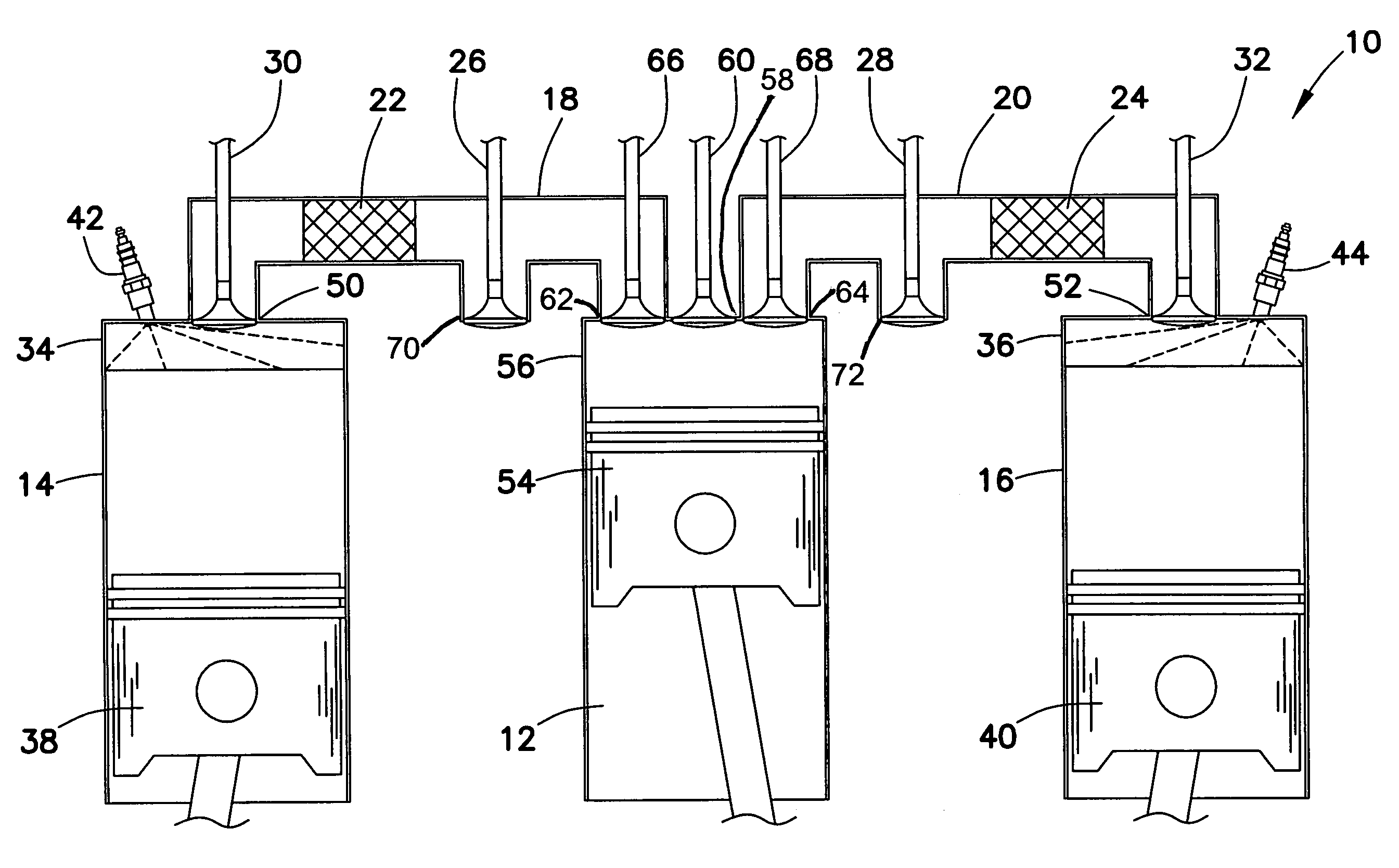
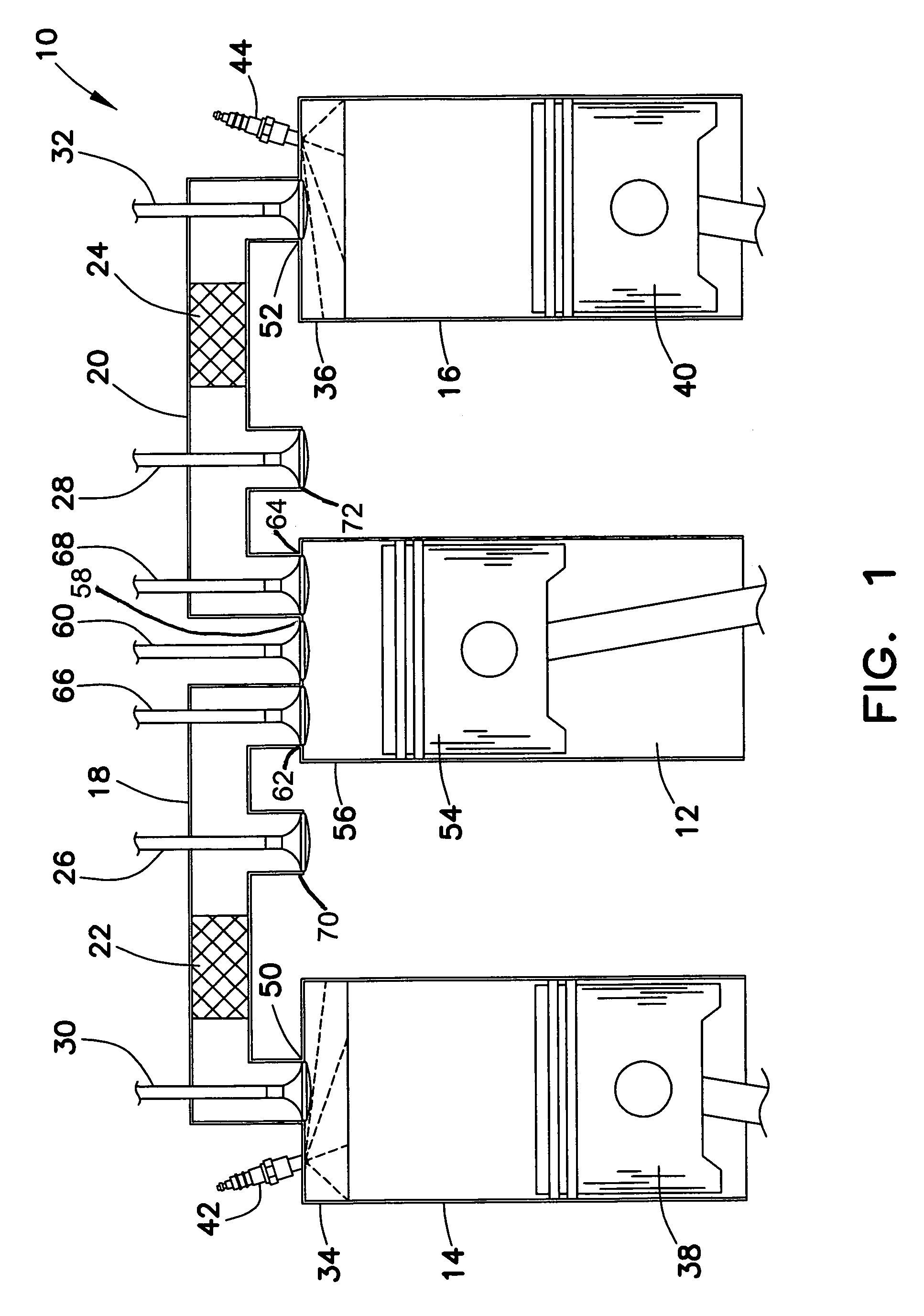
[0020]The thermal transfer internal combustion engine 10 of the present invention, shown in FIG. 1, is an internal combustion engine of typical four-stroke design that utilizes a heat recovery system to increase the thermal efficiency of the engine 10 by recovering the waste heat of the exhaust system. The heat recovery system generally comprises a transfer cylinder 12 positioned between each pair of power cylind...


PUM


Abstract

A thermal transfer internal combustion engine with an air transfer cylinder located between a pair of power cylinders. The transfer cylinder has an intake valve and two transfer valves alternately feeding the two power cylinders. The power cylinders each contain a mono valve used for both intake and exhaust. Counter-flow manifolds connect the mono valves of the power cylinders to the transfer valves of the transfer cylinder. A regenerator with catalytic converter properties is located in each counter-flow manifold. The regenerator is heated by exhaust gases exiting the power cylinders, prior to exiting the engine through exhaust dump valves. Uncompressed intake air is pushed from the transfer cylinder through the regenerator where it is heated and delivered to the power cylinder for conventional processing. The heat recovery system provides high compression temperatures at low compression ratios, reducing engine fuel consumption.

Description

BACKGROUND OF INVENTION[0001]This invention relates to internal combustion engines, and more specifically to internal combustion engines utilizing heat recovery systems to increase engine efficiency.[0002]In a review of internal combustion engines, the gas-fueled Otto engine and the diesel-fueled diesel engine appear to be the only types of engines that have survived the test of time and remain in widespread use.[0003]The diesel engine has a greater thermal efficiency than the Otto engine due to the higher compression ratios of the diesel engines. High compression ratios are employed to achieve high temperatures from the compression.[0004]It is common knowledge that an engine possessing an expansion ratio greater than the compression ratio has a greater work output than a comparable engine where the compression ratio and expansion ratio are the same. In the Otto engine all cylinders have the same swept volume negating the option of increasing the expansion ratio.[0005]It is further ...

Claims


Application Information

Patent Timeline
IPC IPC(8): F02B33/22
CPCF01L1/28F01N5/02F02B41/06F02M31/08F02B21/00F02B2075/125F02G2257/00Y02T10/126Y02T10/16Y02T10/12
Inventor WAIT, IRVING S.
Owner WAIT IRVING S
Why Eureka
Try Eureka