Mask

Inactive Publication Date: 2007-04-10
AUSTRALIAN CENT FOR ADVANCED MEDICAL TECH
View PDF15 Cites 278 Cited by
  • Summary
  • Abstract
  • Description
  • Claims
  • Application Information

AI Technical Summary

Benefits of technology

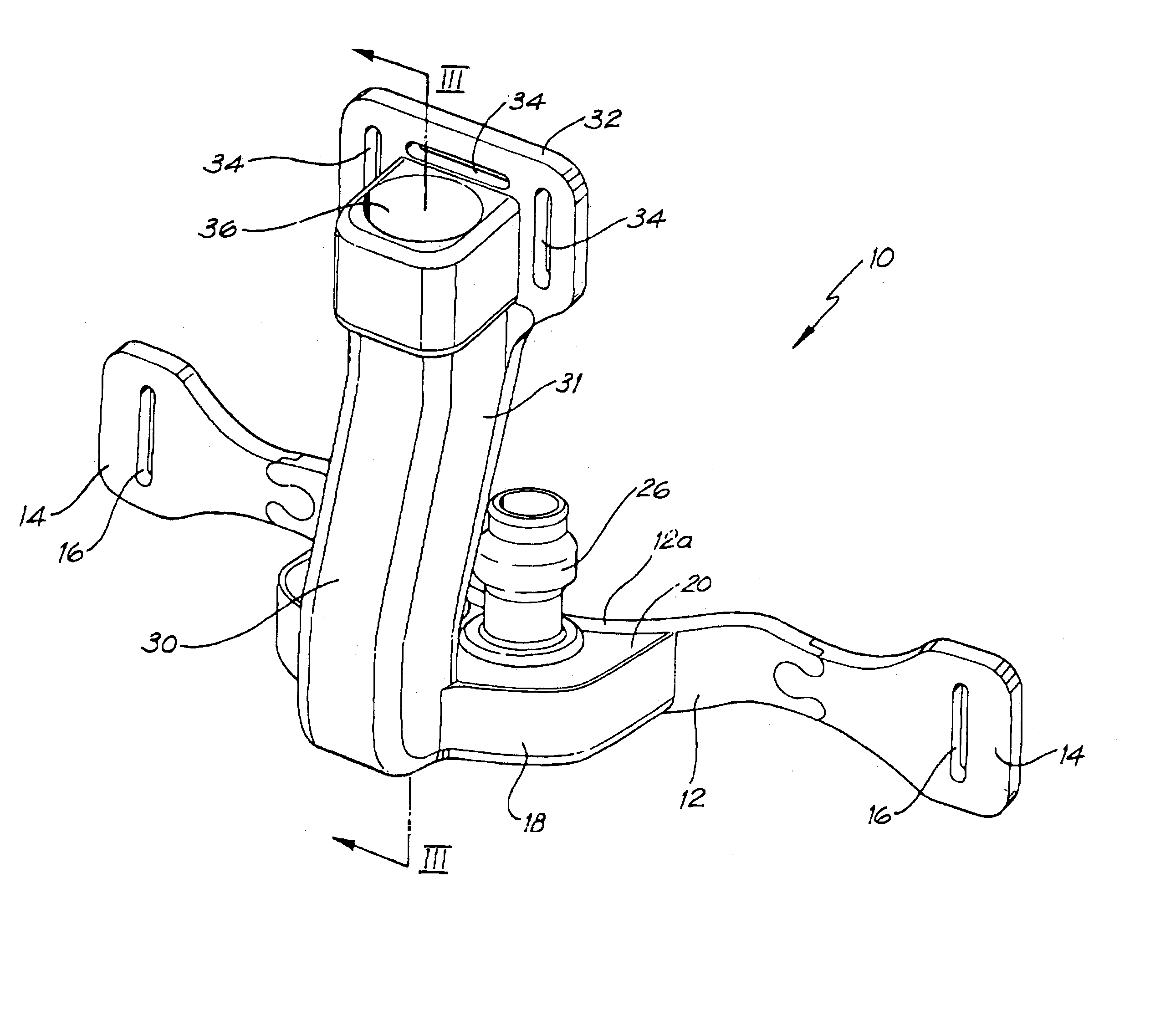
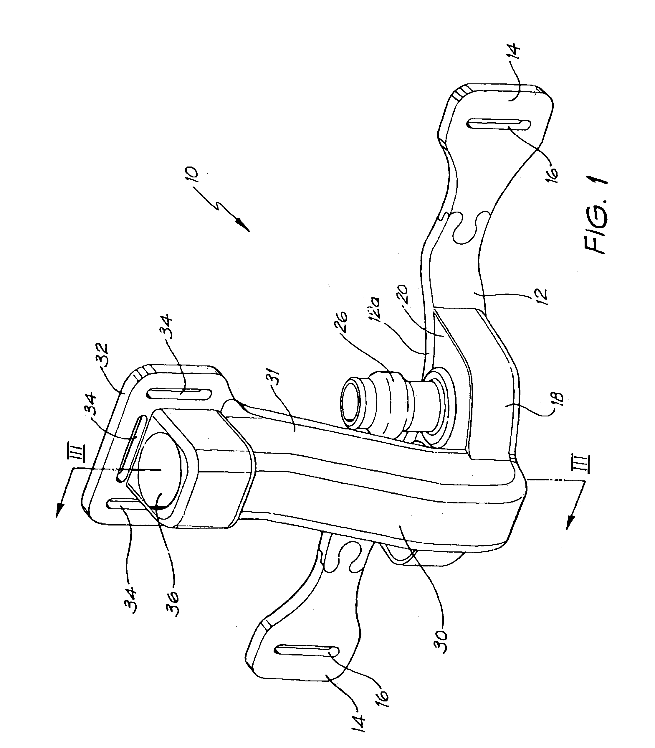
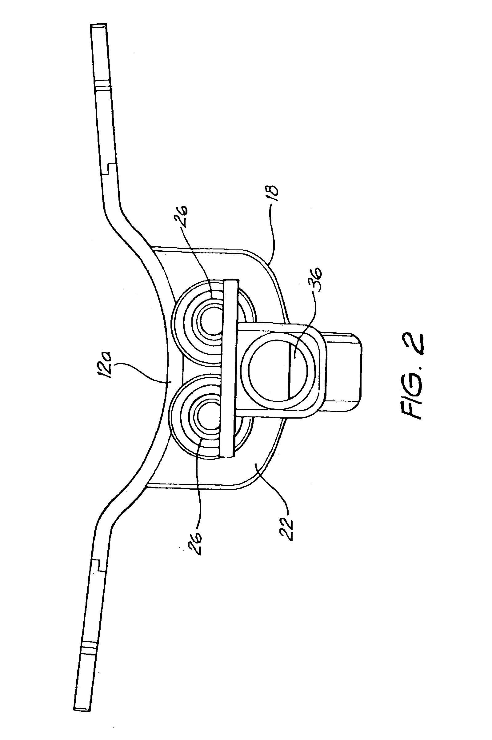
[0026]The advantage of the present invention, in contrast with the prior art U.S. Pat. No. 4,782,832, is that the gas delivery elements do not function as the primary anchor means but merely act as a delivery/sealing means for the air pressure. Instead, anchoring is provided by the strap which provides an elongate anchor means with a large contact area to the face which is therefore very secure, movement being prevented by a high degree of contact by the strap and the skin with consequently high frictional force. The separation of the sealing functions and the anchoring functions is also a major step forward over the bubble type masks of AU 643994 et al where the bubble membrane acts not only as the seal around a patient's nose but also has to anchor the mask to the patient's face. By separating the sealing and anchoring functions the seal is less likely to be broken or adversely affected by movement of the patient's head. The strap is made from a flexible elastomeric material such as silastic and typically the manifold will be formed from the same flexible material so that the manifold

Problems solved by technology

Leaks are undesirable as they can allow the pressure in the mask to drop below a therapeutic level.
Leaks may also be an irritation particularly, if the leak causes jets of air/oxygen to be directed into the patient's eye.
Leaks interrupt a patient's sleep which is undesirable as interrupted sleep is known to be of much less value than uninterrupted sleep.
Leaks may also be noisy.
Movement of the head, and subsequent dislodgment of the mask, and breakage of the seal are major problems with prior art masks.
This is a particular problem when a patient lies on their side, with the side of their head on the pillow as the rigid manifold tends to contact the pillow.
The manifold can also be pushed onto the patient's nose causing discomfort to the patient.
A further problem for all masks is that an air delivery pipe must be attached to the mask at some point.
Movement of the head and the pipe leads to torsion which is transmitted through the hard shell of the manifold and can cause the sealing margins of the mask to rise up and allow a leak.
Whilst both masks produce relatively satisfactory seals they are quite bulky, relatively heavy and ungainly.
They have a substantial impact or “footprint” on the patient's face.
Neither fully solves the problems of forces acting on the manifold causing lea

Method used


Image

  • Mask
  • Mask
  • Mask

Examples


second embodiment

[0080]In the second embodiment, the prongs and upper surface of the manifold are replaced with a flexible shaped “bubble”62, also shown in FIG. 8. The bubble may be made from a flexible elastomeric material (such as silastic). A generally kidney bean shaped opening 64 is provided in the centre of the bubble (see FIG. 9). The bubble ranges in thickness from t1, about 0.2–0.4 mm at the edge around the opening 64 to t2 about 1.5 mm at its base where it joins the manifold (see FIG. 9).

first embodiment

[0081]With reference to FIGS. 11a and 11b, in use, when the mask is correctly positioned on a patient's face with the manifold disposed between the base 101 of the patient's nose and their mouth, the membrane 62 is located below the base 101 of the nose. The relatively thin “bubble” is flexible and when air is admitted under pressure into the manifold the bubble expands and will seal three-dimensionally with the base portion 101 of the patient's nose. FIG. 11b illustrates the unexpanded, non-pressurised shape of the bubble in dashed lines and the pressurised form in complete lines illustrating though slightly exaggerating the expansion of the patient's nose. Air under pressure will flow into the patient's nose through their nares. The patient's nose, in particular their anterior nasal cavities, will also expand (see FIG. 11b) and be pushed outwards. This creates a rolling seal at the nasal (naris) entry margins The seal is formed by the skin around the nostrils (under pressure) push...


PUM


Abstract

A mask (10) for supplying gas under pressure to the nasal airway of a human includes a manifold (30) including means (36) for connection to a gas supply means, a gas supply element or elements (26) for providing said gas to the nasal airway without pressurising the exterior of the nose and a flexible strap (12) formed from an elastomeric material for securing the manifold (30) in position. The strap (12) extends either side of the manifold (30) and is shaped to generally conform with the shape of the upper lip and adjacent cheek area to act as a distributed anchor means for the mask (10).

Description

FIELD OF THE INVENTION[0001]This invention relates to a mask for supplying gases, typically fresh air or oxygen to the airways of humans.BACKGROUND OF THE INVENTION[0002]Various different types of masks are used to provide fresh air or oxygen to the airways of humans. A specialised category of masks is used to provide positive pressure to the human airway. Positive pressure applied in this manner has two different goals.[0003]In a first category, positive pressure is applied to the lungs for the purpose of stabilising the lungs, and in particular for maintaining a minimum inflation level of the small air spaces in which gas transfer occurs (the alveoli). This therapy is very useful in patients with a variety of lung diseases, where the disease process tends to lead to collapse (closure of the airway containing regions of the lung).[0004]In a second category, the positive pressure is applied to the nasal airway with the intention of maintaining the pressure in, and the patency of, th...

Claims


Application Information

Patent Timeline
IPC IPC(8): A61M15/08A62B18/02A61M16/06A61M16/20
CPCA61M16/06A61M16/0666A61M16/0683A61M16/0616A61M16/0633A61M16/208A61M2210/0618
Inventor WILKIE, PAULSULLIVAN, COLIN
Owner AUSTRALIAN CENT FOR ADVANCED MEDICAL TECH
Why Eureka
Try Eureka