Constant voltage circuit and constant current source, amplifier, and power supply circuit using the same

a constant current source and constant voltage technology, applied in the direction of process and machine control, instruments, machines without intermediate ac conversion, etc., can solve the problem that the circuit itself is more susceptible to noise, and achieve the effect of reducing the rise time of output voltage and quick charge of capacitors

Inactive Publication Date: 2007-04-10
RICOH ELECTRONIC DEVICES CO LTD
View PDF5 Cites 37 Cited by
  • Summary
  • Abstract
  • Description
  • Claims
  • Application Information

AI Technical Summary

Benefits of technology

[0008]Accordingly, it is a general object of the present invention to provide a constant voltage circuit in which the above-described disadvantages are eliminated.
[0009]A more specific object of the present invention is to provide a constant voltage circuit that can quickly charge a capacitor for noise prevention without detecting the charge voltage of the capacitor and thus reduce time before the output voltage reaches a predetermined constant voltage.
[0015]According to a constant voltage circuit and a constant current source, an amplifier, and a power supply circuit using the constant voltage circuit according to the present invention, a switch circuit part charges a second capacitor by applying an input voltage thereto and blocks the discharging of the second capacitor to a first capacitor when a constant voltage generator circuit part is caused to stop outputting a predetermined constant voltage by a control signal, and stops applying the input voltage to the second capacitor and charges the first capacitor by releasing an electric charge stored in the second capacitor to the first capacitor when the constant voltage generator circuit part is caused to start outputting the predetermined constant voltage by the control signal. Accordingly, by setting a predetermined relationship among the capacitance of the first capacitor, the capacitance of the second capacitor, and the voltages at the time of charging, it is possible to quickly charge the first capacitor to a desired voltage without detecting the charge voltage of the first capacitor. Accordingly, there is no need of voltage detection means that adversely affects a circuit. Further, it is possible to quickly charge the capacitor for noise prevention, so that it is possible to substantially reduce the rise time of the output voltage of the constant voltage circuit and time before a circuit using the constant voltage circuit is stabilized.

Problems solved by technology

Consequently, the circuits themselves have become more susceptible to noise, so that a capacitor for noise absorption is provided in the circuits.
However, the constant voltage circuit 100 shown in FIG. 1 has a problem in that the current used therein is extremely small so that it takes time before the capacitor 102 for noise control is charged to a predetermined voltage, thus requiring time before the output voltage of the constant voltage circuit 100 reaches the predetermined constant voltage Vo1.

Method used


Image

  • Constant voltage circuit and constant current source, amplifier, and power supply circuit using the same
  • Constant voltage circuit and constant current source, amplifier, and power supply circuit using the same
  • Constant voltage circuit and constant current source, amplifier, and power supply circuit using the same

Examples


Embodiment Construction

[0025]A description is given below, with reference to the accompanying drawings, of an embodiment of the present invention.

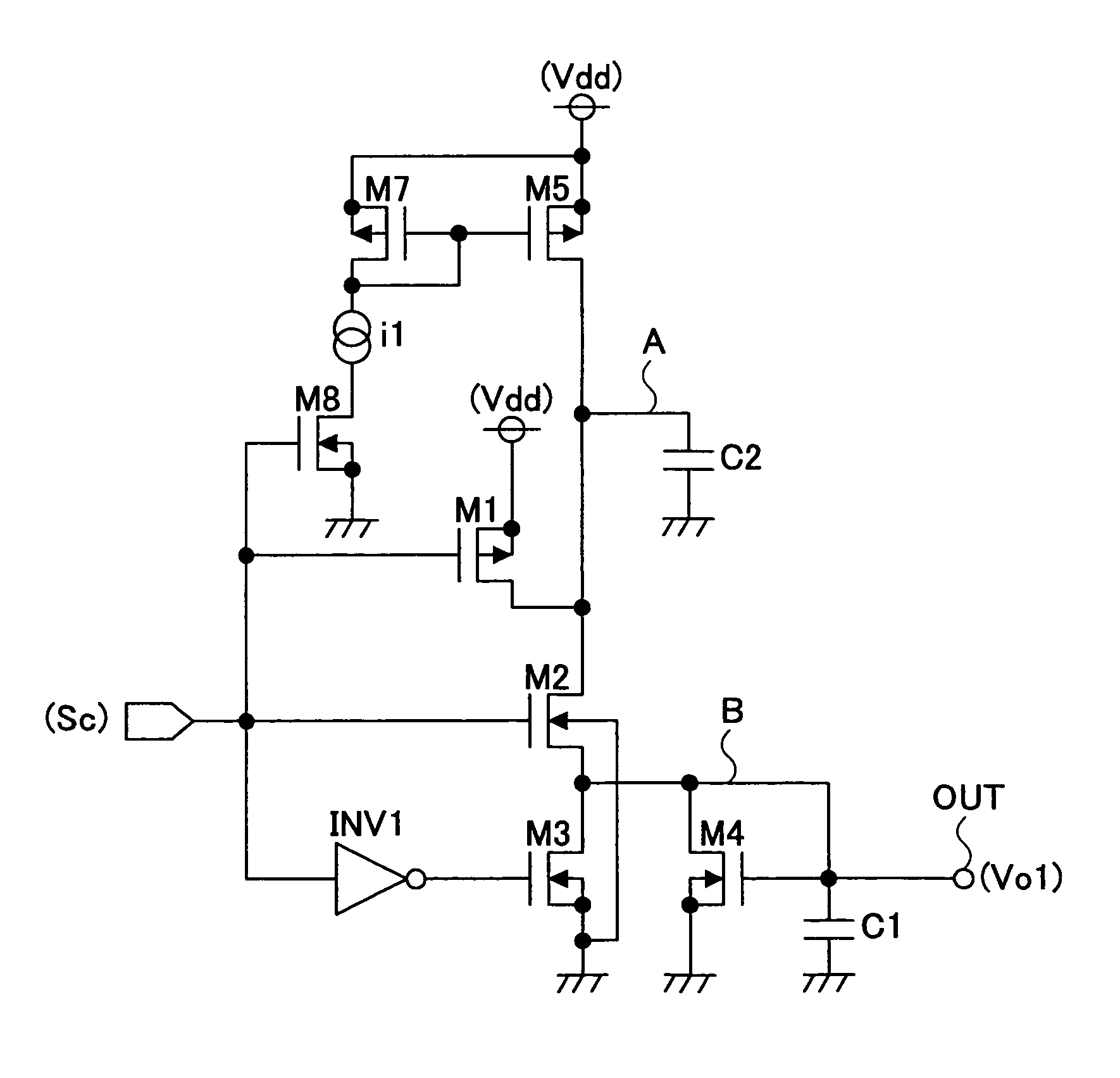
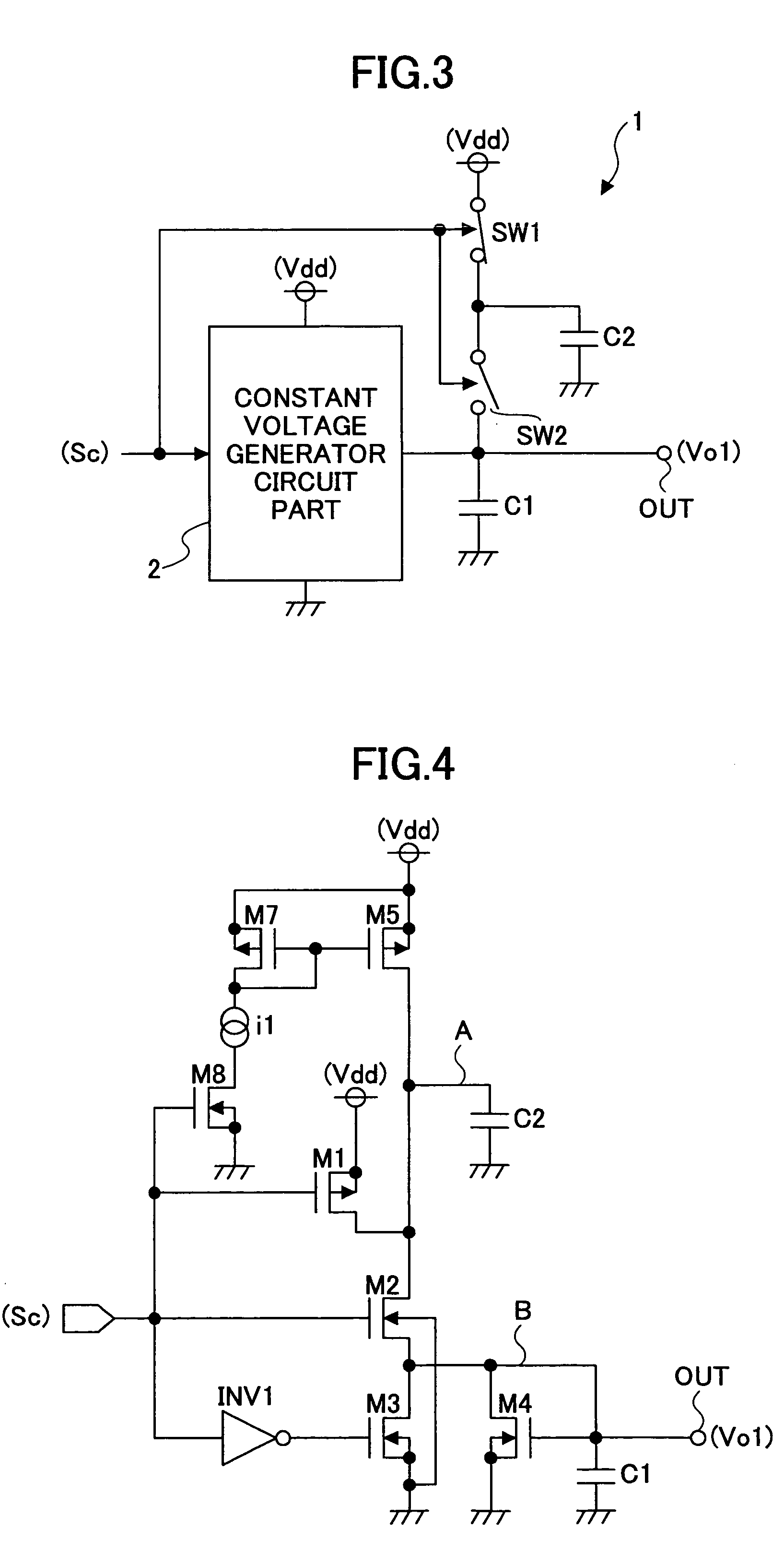
[0026]FIG. 3 is a schematic circuit diagram showing a constant voltage circuit 1 according to the embodiment of the present invention.

[0027]Referring to FIG. 3, the constant voltage circuit 1 generates a predetermined constant voltage V1 from an input voltage Vdd that is supply voltage, and outputs the generated voltage V1 from an output terminal OUT as an output voltage Vo1.

[0028]The constant voltage circuit 1 includes a constant voltage generator circuit part 2 generating the predetermined constant voltage V1 and outputting it as the output voltage Vo1, capacitors C1 and C2 for noise prevention, and switches SW1 and SW2. The output end of the constant voltage generator circuit part 2 is connected to the output terminal OUT. The capacitor C1 is connected between the output terminal OUT and ground. The capacitor C1 forms a first capacitor, the capacitor C2 forms...


PUM


Abstract

A constant voltage circuit is disclosed that includes a constant voltage generator circuit part converting an input voltage into a predetermined constant voltage in accordance with an externally input control signal and outputting the constant voltage; a first capacitor connected to the output end of the constant voltage generator circuit part; a second capacitor charging the first capacitor; and a switch circuit part controlling charging and discharging of the second capacitor in accordance with the control signal. The switch circuit part charges the second capacitor and blocks the discharging of the second capacitor to the first capacitor when the constant voltage generator circuit part is caused to stop outputting the constant voltage by the control signal, and stops applying the input voltage to the second capacitor and charges the first capacitor when the constant voltage generator circuit part is caused to start outputting the constant voltage by the control signal.

Description

BACKGROUND OF THE INVENTION[0001]1. Field of the Invention[0002]The present invention relates generally to constant voltage circuits, constant current sources, amplifiers, and power supply circuits, and more particularly to a constant voltage circuit capable of reducing the charge time of a capacitor for noise prevention, and a constant current source, an amplifier, and a power supply circuit using the constant voltage circuit.[0003]2. Description of the Related Art[0004]In recent years, there has been a demand for power saving also in terms of environmental measures. The importance of reduction in power consumption in apparatuses using batteries, such as cellular phones and digital cameras, is increasing also in terms of extending the useful service life of the batteries. As a result, in those apparatuses, the bias current of an amplifier circuit and the current consumed in a constant voltage circuit such as a reference voltage generator circuit are extremely reduced. Consequently,...

Claims


Application Information

Patent Timeline
Patent Type & Authority Patents(United States)
IPC IPC(8): G05F3/16
CPCH02M3/07G05F1/575
Inventor ITOH, KOHZOH
Owner RICOH ELECTRONIC DEVICES CO LTD
Why Eureka
Try Eureka