Object identification using quantum dots fluorescence allocated on Fraunhofer solar spectral lines

a technology of quantum dots and solar spectral lines, applied in the field of optical identification systems, can solve the problems of increasing the casualty rate of so-called “friendly fire” incidents, falling into disuse, and unable to identify friendly from unfriendly forces, and achieve the effect of convenient deploymen

Inactive Publication Date: 2007-04-10
NAT RES COUNCIL OF CANADA
View PDF10 Cites 40 Cited by
  • Summary
  • Abstract
  • Description
  • Claims
  • Application Information

AI Technical Summary

Benefits of technology

[0008]The present invention provides an optical based identification system that is easily deployable and can be used in broad daylight. Fluorescent semiconductor nanocrystals (quantum dots) that fluoresce at specific wavelengths are distributed in a suitable polymer. The resulting mixture can then be applied as paint or on an adhesive label for application to a portion of any equipment or member of a friendly unit. The system also has a corresponding detection processing unit which may be mounted on ordnance or on any other equipment such as aircraft. The detection unit uses a laser, which when active, causes a laser beam to strike the paint or adhesive able applied to the friendly unit. This causes the quantum dots to fluoresce. The fluorescence of the quantum dots can be detected by the sensor portion of the detection / processing unit. The sensor portion then transmits the data generated by the detected fluorescence to a data processing unit. The unit can then send a corresponding signal to the equipment operator or, if the unit is mounted on ordnance that has been launched to the warhead to deactivate the warhead. To overcome the effects of broad daylight on an optical system, the quantum dots are engineered to fluoresce at wavelengths corresponding to the absorption lines of the solar ultra-violet to the near infrared spectrum, more commonly known as Fraunhofer lines.

Problems solved by technology

From the time man first engaged in organized combat, one of the issues he has faced has been the identification of friendly forces.
However, this practice has, for obvious reasons, fallen into disuse.
The problem of identifying friendly from unfriendly forces, however, remains.
The rise of so-called “smart weapons” has increased the accuracy of ordnance delivery, but, sadly, has also increased the casualty rates of so-called “friendly fire” incidents.
While this system would be effective for vehicles, it is not suitable for individual soldiers and is costly.
However, all of these alternatives are quite costly on a per unit basis and do not offer a solution which can be easily deployable or be deployable to the single soldier level.
None of these systems can also be deployable on ordnance.
Such ordnance, once launched, cannot be aborted.
Thus, a targeting error can lead to tragic results.
One possible problem with optics-based solutions in their use in broad daylight.
Specifically, detecting a return optical signal can be difficult as the return optical signal can get overwhelmed by sunlight.

Method used


Image

  • Object identification using quantum dots fluorescence allocated on Fraunhofer solar spectral lines
  • Object identification using quantum dots fluorescence allocated on Fraunhofer solar spectral lines
  • Object identification using quantum dots fluorescence allocated on Fraunhofer solar spectral lines

Examples


Embodiment Construction

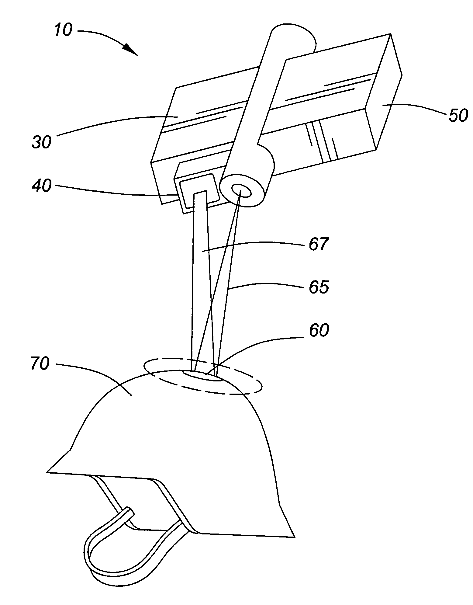
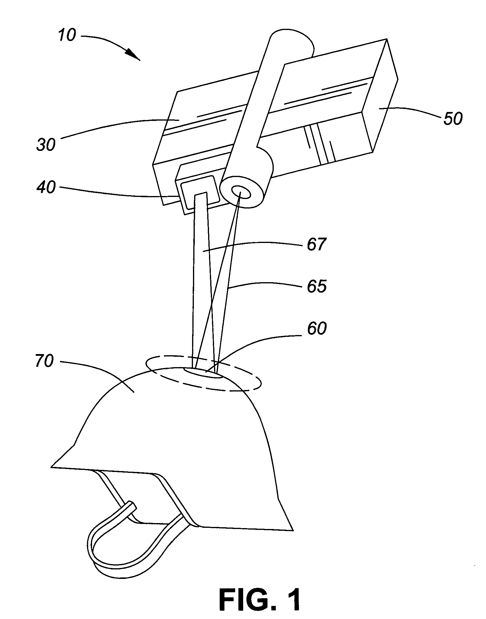
[0027]Referring to FIG. 1, a partial optics based identification system 10 is illustrated. The partial system 10 has a laser 20, a spectrum sensor 30, a spectral filter 40, and a data processing module 50. The rest of the system consists of a coating 60 deposited on a piece of equipment 70, in this case a military combat helmet.

[0028]The system functions with the laser 20 providing an optical beam 65 which hits the coating 60. This causes the coating to fluoresce and emit a corresponding electromagnetic radiation (fluorescence) 67. The radiation 67 is picked up by the spectrum sensor 30 after being filtered by the spectral filter 40. The spectrum sensor 30 then transmits what is detected to the data processing module 50. The data processing module 50 then processes or decodes any data encoded in the fluorescence. Based on the decoded data, the data processing module 50 may then send an appropriate signal to an external module or to an end user.

[0029]To overcome the issue of sunlight...


PUM


Abstract

An optical based identification system that is easily deployable and can be used in broad daylight. Fluorescent semiconductor nanocrystals (quantum dots) that fluoresce at specific wavelengths are distributed in a suitable polymer. The resulting mixture can then be applied as paint or on an adhesive label for application to a portion of any equipment or member of a friendly unit. The system also has a corresponding detectional processing unit which may be mounted on ordnance or on any other equipment such as aircraft. The detection unit uses a laser, which when active, causes a laser beam to strike the paint or adhesive able applied to the friendly unit. This causes the quantum dots to fluoresce. The fluorescence of the quantum dots can be detected by the sensor portion of the detection / processing unit. The sensor portion then transmits the data generated by the detected fluorescence to a data processing portion detection / processing unit such as a corresponding signal to the equipment operator or, if the unit is mounted on ordnance that has been launched to the warhead to deactivate the warhead. To overcome the effects of broad daylight on an optical system, the quantum dots can be detected by the sensor portions of the detection / processing unit. The sensor portion then transmits the data generated by the detected fluorescence to a data processing portion which decodes the data. If the decoded data indicates a friendly unit, the detection / processing unit sends a corresponding signal to the equipment operator or, if the unit is mounted on ordnance that has been launched to the warhead to deactivate the warhead. To overcome the effects of broad daylight on an optical system, the quantum dots are engineered to fluoresce at wavelengths corresponding to the absorption lines of the solar spectrum, more commonly known as Fraunhofer lines.

Description

FIELD OF THE INVENTION[0001]The present invention relates to identification systems and, more specifically, relates to optical identification systems which may be used in broad daylight in both military and civilian applications.BACKGROUND TO THE INVENTION[0002]From the time man first engaged in organized combat, one of the issues he has faced has been the identification of friendly forces. Prior to the widespread use of drab coloured uniforms for low visibility, brightly coloured uniforms were used to identify one group of soldiers from another. However, this practice has, for obvious reasons, fallen into disuse. The problem of identifying friendly from unfriendly forces, however, remains.[0003]One area in which this problem is critical, if not potentially fatal, is in the delivery of ordnance. The rise of so-called “smart weapons” has increased the accuracy of ordnance delivery, but, sadly, has also increased the casualty rates of so-called “friendly fire” incidents. In the first ...

Claims


Application Information

Patent Timeline
Patent Type & Authority Patents(United States)
IPC IPC(8): G06K9/74
CPCG06K19/06084G06K7/12B82Y15/00B82Y20/00Y10T428/2852
Inventor CHANG, SHOUDEZHOU, MING
Owner NAT RES COUNCIL OF CANADA
Why Eureka
Try Eureka