Speaker

a technology for speakers and speakers, applied in the field of speakers, can solve the problems of difficult difficult to reduce speakers, and insufficient improvement of the distortion and quality of sound, so as to improve the performance of speakers, reduce the harmonizing distortion of speakers, and improve power linearity

Active Publication Date: 2007-04-10
PANASONIC CORP
View PDF15 Cites 10 Cited by
  • Summary
  • Abstract
  • Description
  • Claims
  • Application Information

AI Technical Summary

Benefits of technology

[0025]The suspension is formed using the first edge and second edge as discussed above, a damper causing the nonlinearity and asymmetry can be omitted. Additionally, the second edge is configured to cancel the asymmetry of the first edge, and hence the nonlinearity and asymmetry of the suspension can be essentially solved. Thus, the harmonic distortion of the speaker can be reduced, the power linearity can be improved, and the performance of the speaker can be improved. A part from the bent section to the inner periphery of the diaphragm is supported by the suspension holder, so that the diaphragm is not required to be conical for securing rigidity thereof but even a flat diaphragm can be sufficiently rigid. Securing rigidity of diaphragm does not require large thickness thereof, so that the speaker of the present invention can be thinned.

Problems solved by technology

In the speaker having the conventional configuration, however, the improvement of the distortion and quality of the sound is not sufficiently effective and thinning of the speaker is difficult.
As long as damper 8 is combined with edge 6 to form the suspension, it is difficult to improve performance of the speaker by solving the asymmetry and especially the nonlinearity and reducing the harmonic distortion.

Method used


Image

  • Speaker
  • Speaker
  • Speaker

Examples


exemplary embodiment 1

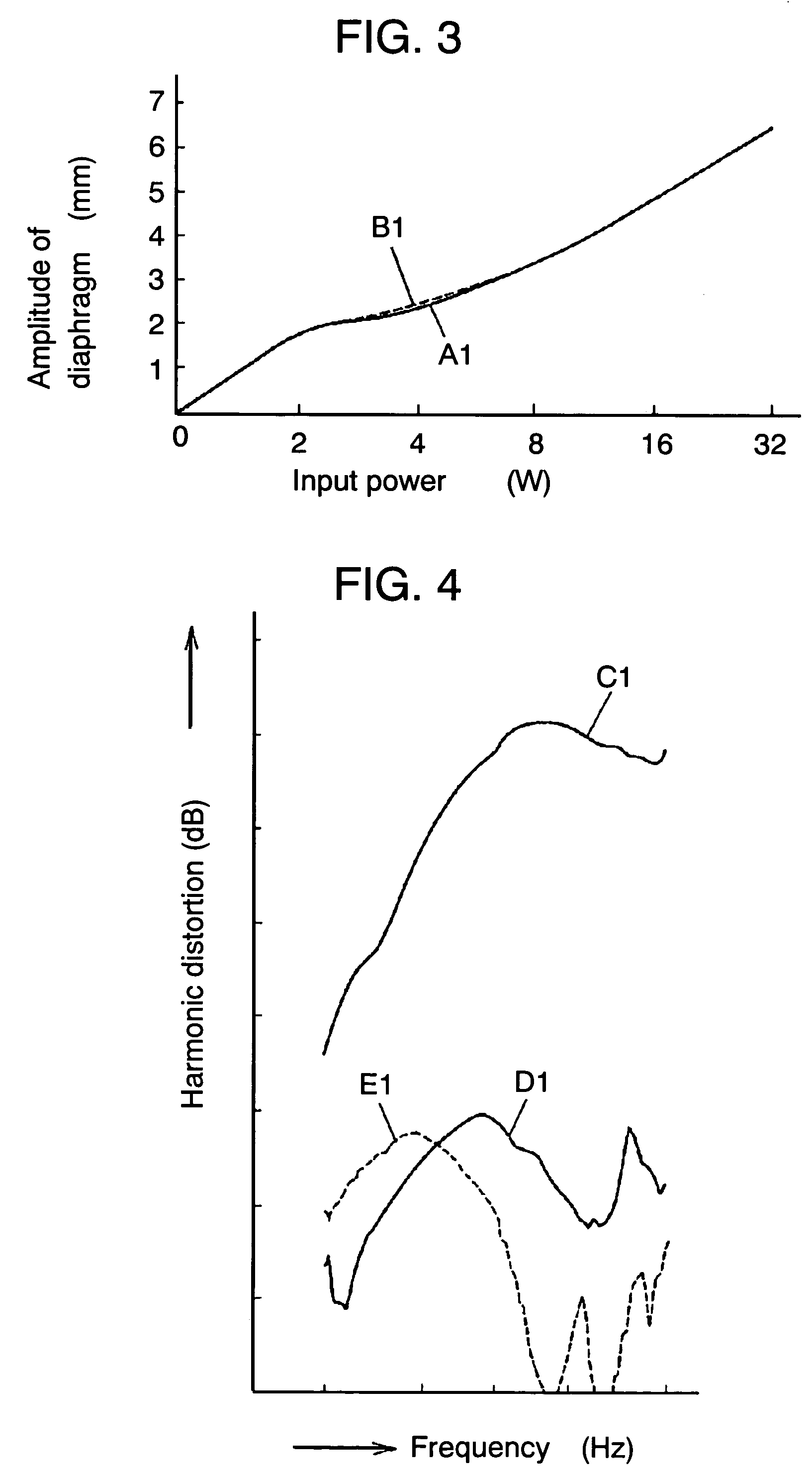
[0063]FIG. 3 shows amplitude of diaphragm 16 with respect to input power, namely power linearity, of the speaker of exemplary embodiment 1 of the present invention. Curve A1 shows a diaphragm amplitude characteristic with respect to input power to the magnetic circuit 9 side. Curve B1 shows a diaphragm amplitude characteristic with respect to input power to the opposite side to the magnetic circuit 9.

[0064]FIG. 4 shows harmonic distortion characteristics of the speaker of exemplary embodiment 1, and shows that the larger the dynamic range of the output sound pressure and the harmonic distortion is, the lower the harmonic distortion is. Curve C1 shows an output sound pressure characteristic, curve D1 shows a second harmonic distortion characteristic, and curve E1 shows a third harmonic distortion characteristic.

[0065]Operations of the speaker of exemplary embodiment 1 having the configuration discussed above are described hereinafter.

[0066]When an electric signal output from an audio...

exemplary embodiment 3

[0090](Exemplary embodiment 3)

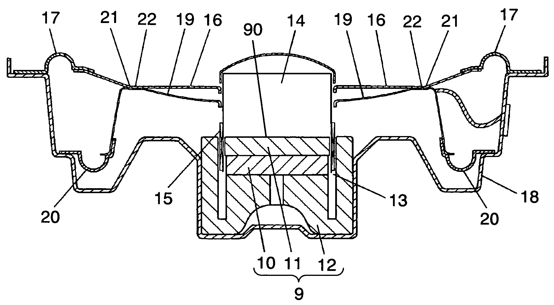
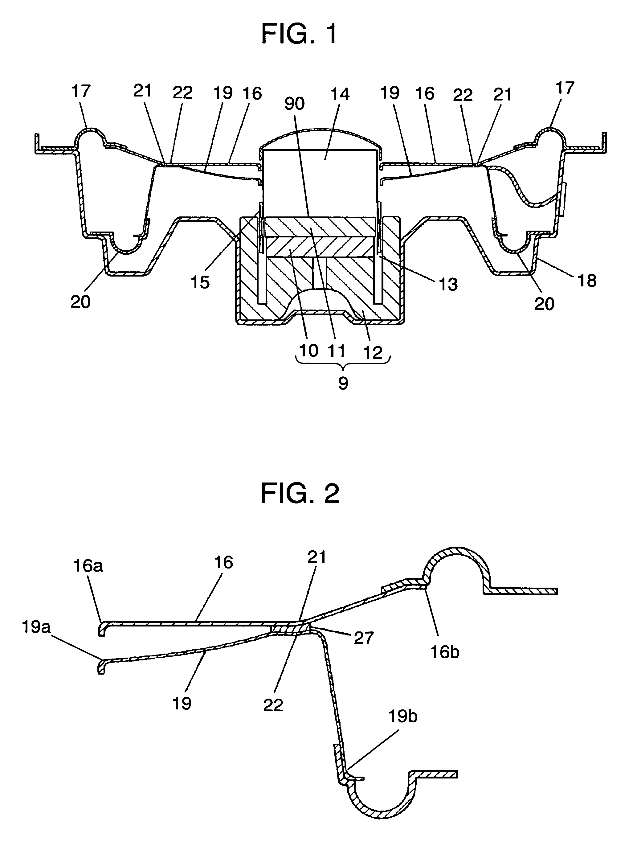
[0091]A speaker in accordance with exemplary embodiment 3 of the present invention is described with reference to FIG. 9. The basic configuration of the speaker is similar to that of the speaker of embodiment 1 of the present invention, but the speaker of embodiment 3 differs from the speaker of embodiment 1 in that the outer periphery of suspension holder 19 is coupled through the second edge 20, on the bottom side of magnetic circuit 9, and below top surface 90 of plate 11.

[0092]Thanks to the configuration of FIG. 9, the distance between fulcrums of first edge 17 and second edge 20 can be made as long as possible, so that rolling of voice coil body 14 during moving can be minimized. In other words, the original position of voice coil body 14 during moving lies between the coupling point of first edge 17 with frame 18, namely the fulcrum of voice coil body 14, and the coupling point of second edge 20 with frame 18. The original position of voice coil b...


PUM


Abstract

A speaker has a diaphragm (16) and a suspension holder (19) supporting the diaphragm from the back surface of the diaphragm. The diaphragm has a bent section (21) disposed between its outer periphery and its inner periphery, with the portion to the outer periphery having a conical shape. The diaphragm is coupled to the suspension holder at the bent section. This configuration can omit a damper that causes nonlinearity and asymmetry of suspension, to reduce the harmonic distortion of the speaker and improve the power linearity and the performance of the speaker. The diaphragm can have a flat configuration at its inner peripheral portion, can be secured with sufficient rigidity, and can be rigidly secured to a frame of the sneaker. This can reduce the thickness of the diaphragm and enable formation of a smaller, low profile sneaker can be realized.

Description

[0001]This application is a U.S. National Phase Application of PCT International Application PCT / JP02 / 07426.TECHNICAL FIELD[0002]The present invention relates to a speaker used for various audio apparatuses.BACKGROUND ART[0003]FIG. 24 shows a conventional speaker. The conventional speaker has the following elements:[0004]magnetic circuit 1;[0005]voice coil body 4 having coil section 3 movable in magnetic gap 2;[0006]diaphragm 5 of which inner periphery is coupled to voice coil body 4 and outer periphery is coupled to frame 7 via edge 6; and[0007]damper 8 of which inner periphery is coupled to voice coil body 4 and outer periphery is coupled to frame 7.[0008]In the conventional speaker, when an electric signal output from an audio amplifier or the like is fed into coil section 3, voice coil body 4 vibrates, the vibromotive force is transmitted to diaphragm 5, and diaphragm 5 vibrates air to convert the electric signal to voice. Damper 8 is combined with edge 6 to form a suspension to...

Claims


Application Information

Patent Timeline
Patent Type & Authority Patents(United States)
IPC IPC(8): H04R25/00H04R9/02H04R7/12H04R7/26H04R9/04H04R9/06
CPCH04R7/26H04R9/06H04R7/16H04R9/043
Inventor FUNAHASHI, OSAMUMORIMOTO, HIROYUKI
Owner PANASONIC CORP
Why Eureka
Try Eureka