Device for monitoring medical equipment

a technology for monitoring devices and medical equipment, applied in the field of medical devices, to achieve the effects of high probability, low cost, and high reliability

Inactive Publication Date: 2007-04-10
STORZ ENDOSKOP PROD GMBH
View PDF8 Cites 83 Cited by
  • Summary
  • Abstract
  • Description
  • Claims
  • Application Information

AI Technical Summary

Benefits of technology

[0016]The invention is based on the object of providing safety monitoring of medical instruments, in particular of generators for high-frequency surgery, which can detect internal faults and also external operating faults with a high probability, and at the same time is of highest reliability and low cost.
[0020]This kind of arrangement in accordance with the invention is substantially safer and more reliable than the known arrangements which have a second main controller. In accordance with the invention, checks are not made by comparison with a redundant system, but in a second, different and independent way. They are performed, for example, with hardware of a completely different kind, together with different software based on different working procedures and basic principles. This substantially reduces systematic errors in hardware and software.
[0021]In another embodiment of the invention, setting elements are provided for presetting values and selecting functions exclusively for the purpose of controlling the safety controller. With this separate provision of setting elements, any possibility of the safety controller being affected by other defective component parts, particularly those governed by the main controller, can be excluded. Thus, for example, for the purpose of setting certain particularly critical instrument functions, it is possible to provide simultaneous confirmation by means of two switches or keys. For this, a first key controls the main controller whilst a second key signals an activation of a function to the safety controller. By this means, any unintended performance of an instrument function by an inadvertent actuation of a key is excluded, and at the same time it is possible to avoid defective component parts or componentry from affecting the safety controller.
[0024]In a further advantageous embodiment of the invention, sampling taps or sensors, connected to functional elements, are provided for transmitting information concerning the instrument status exclusively to the safety controller. With this design, having redundant measurement taps or sensors, even errors caused by faulty sampling taps or sensors that communicate with the main controller can be detected. For example, if a defective output voltage measurement causes an instrument to supply a voltage which is too high, but has been signaled to the main controller as being correct, then a safety controller which uses the same output voltage measurement would also accept the value as being correct. However, by means of an additional output voltage measurement, a safety controller can detect that too high an output voltage is being supplied and thereupon deactivate the instrument.
[0025]In a particularly advantageous embodiment of the invention, control elements or circuit elements are provided to enable only the safety controller to deactivate the entire instrument or functional elements, or to affect their working. This can prevent a superposition of different control signals, for example, signals from a defectively functioning main controller with signals from a safety controller that attempts to deactivate the instrument, or to put it into a safe condition.

Problems solved by technology

Furthermore, in the case of unacceptable operating conditions or errors, the safety controller issues an error signal which deactivates or puts the functional elements into a safe operating condition.

Method used


Image

  • Device for monitoring medical equipment
  • Device for monitoring medical equipment

Examples


Embodiment Construction

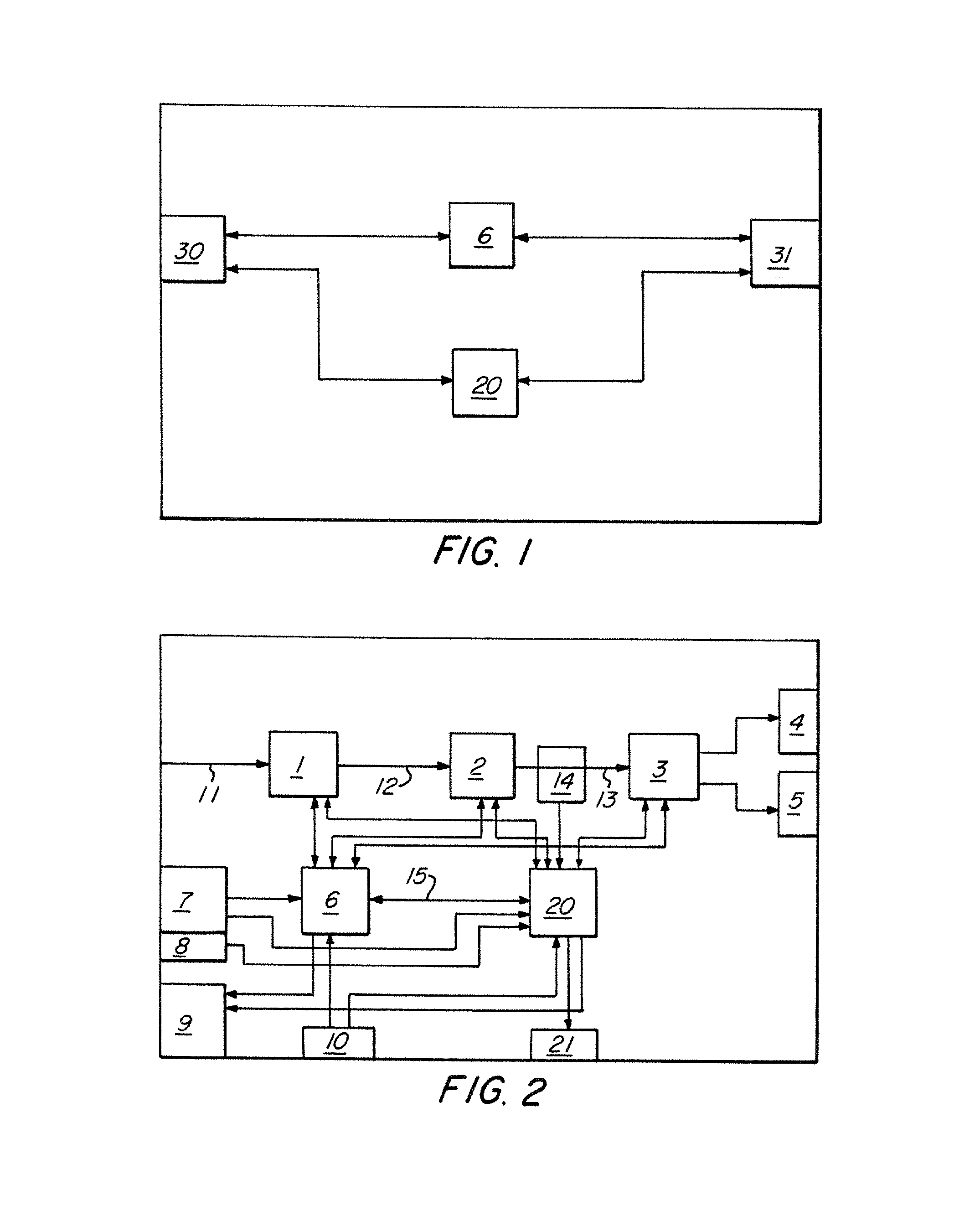
[0032]FIG. 1 schematically shows a device according to the invention. In a medical instrument, operating parameters are preset by means of setting elements 30. Interrogation of these setting elements is effected by a main controller 6 which suitably sets and controls the functional elements 31. Furthermore, a safety controller 20 is present, which also performs an interrogation concerning parameters of the setting elements, and uses these, together with the measured values of the functional elements, to perform a plausibility check. In case of an error, the system is put into a safe operating condition, or is shut-down, by the safety controller. Optionally, the safety controller may operate independently from the main controller, or may ask the main controller for additional information, in particular concerning correct working of the main controller.

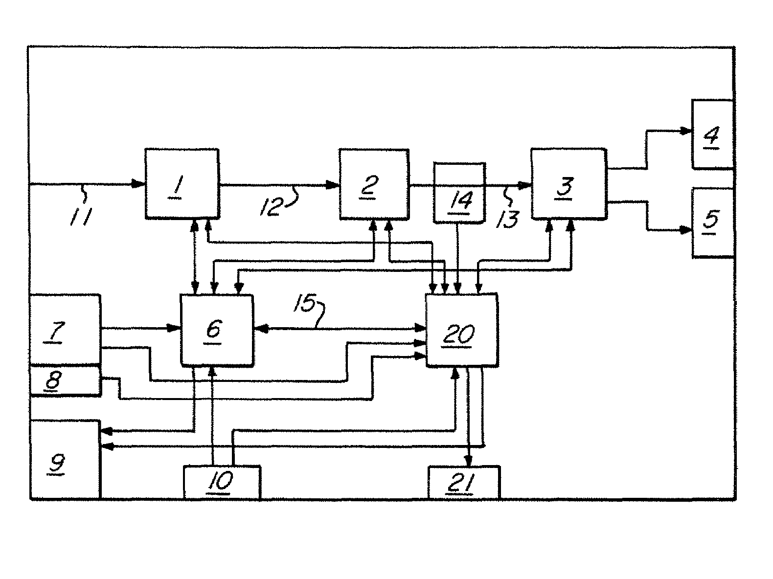
[0033]FIG. 2 shows the invention clearly for the case of a high-frequency energy generator. A generator for high-frequency surgery com...


PUM


Abstract

A medical instrument, in particular a generator for high-frequency surgery, comprises setting elements for presetting functions, and also functional elements for performing functions according to the settings. A controller interrogates the setting elements and controls the functional elements accordingly. Furthermore, a safety controller is provided for performing plausibility checks with the aid of information from the setting elements and also the functional elements, and for deactivating, or putting into a safe operating condition, the functional elements in the case of inadmissible working conditions.

Description

CROSS REFERENCE TO RELATED APPLICATIONS[0001]This application is a continuation of pending International Application No. PCT / IB03 / 03023 filed on Apr. 28, 2003, which designated the United States and claims priority from the German Application No. 102 18 894.7 filed on Apr. 26, 2002.BACKGROUND OF THE INVENTION[0002]The invention relates to a medical instrument, and in particular to a generator for power generation for high-frequency surgery.[0003]1. Field of the Invention[0004]In the case of medical instruments, a matter of foremost concern, apart from that of the actual treatment, is the safety of patients and of persons performing the treatment. Many medical instruments act on a patient by means of electrical or mechanical energy, or require internal electrical or mechanical energy for a performance of their functions. Because of these forms of energy, any faulty handling or malfunction of an instrument may endanger patients or persons performing a treatment. The potential danger w...

Claims


Application Information

Patent Timeline
Patent Type & Authority Patents(United States)
IPC IPC(8): G05B9/02A61B18/18A62B1/04H04N7/18A61B18/12G06F11/00
CPCA61B18/1233
Inventor DANERS, FELIX
Owner STORZ ENDOSKOP PROD GMBH
Why Eureka
Try Eureka