Control device for multi-cylinder internal combustion engine and signaling device capable of providing same with information
a multi-cylinder internal combustion engine and control device technology, applied in the direction of electrical control, process and machine control, instruments, etc., can solve the problems of generating exhaust gas and wasting fuel, aggravating exhaust emissions, and inability to perform idle stop
- Summary
- Abstract
- Description
- Claims
- Application Information
AI Technical Summary
Benefits of technology
Problems solved by technology
Method used
Image
Examples
embodiment 1
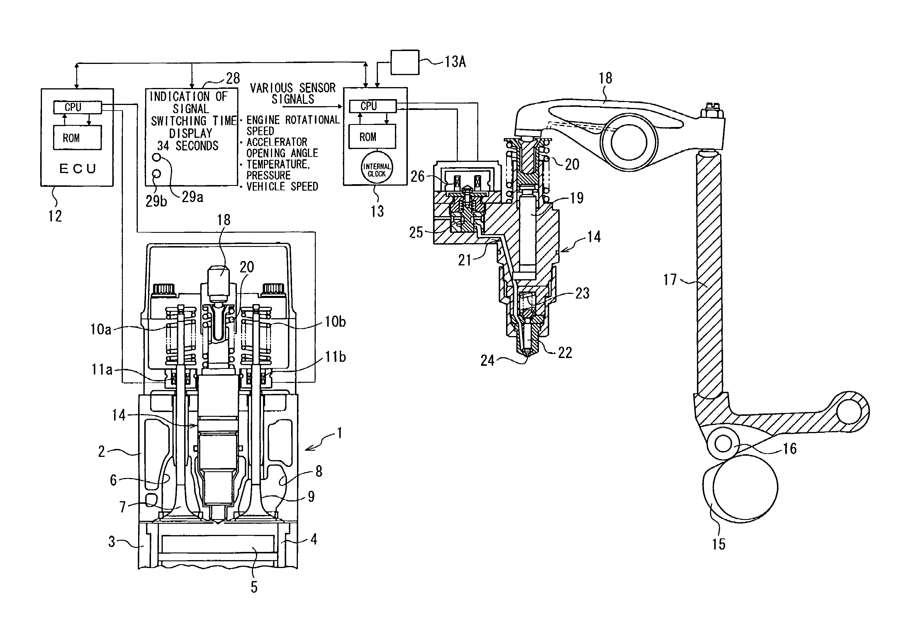
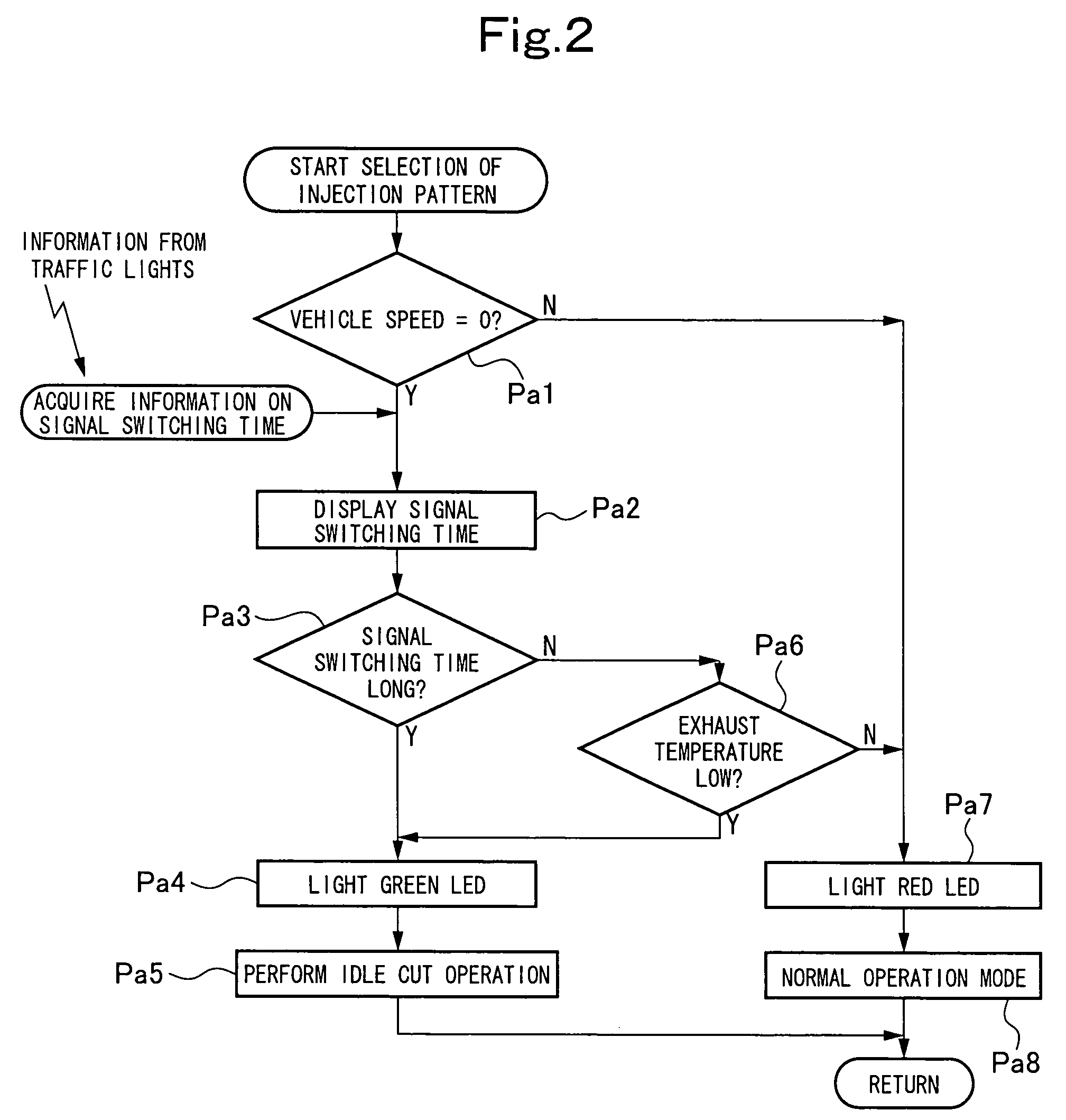
[0037]FIG. 1 is a structural explanation drawing of a multi-cylinder internal combustion engine in a vehicle, such as an automobile, showing Embodiment 1 of the present invention. FIG. 2 is a flow chart for selection of an injection pattern. FIG. 3 is a flow chart for an idle cut operation. FIG. 4 is a flow chart for determination of an idle cut cylinder. FIG. 5 is an explanation drawing of means for acquiring information on a traffic signal switching time.
[0038]As shown in FIG. 1, a multi-cylinder internal combustion engine (hereinafter referred to simply as an engine) 1 having six cylinders, for example, is composed of a cylinder head 2 and a cylinder block 3. A piston 5 is slidably housed in each cylinder of the cylinder block 3 via a cylinder liner 4.
[0039]Each cylinder of the cylinder head 2 is provided with an intake valve 7 for opening and closing an intake port 6, and an exhaust valve 9 for opening and closing an exhaust port 8. The intake valve 7 and the exhaust valve 9 are...
embodiment 2
[0059]FIG. 6 is a flow chart for selecting an injection pattern showing Embodiment 2 of the present invention.
[0060]In the controlling actions of the electronic control units (ECU) 12, 13 in Embodiment 1, after determination of the vehicle speed (see Step Pc1), the battery voltage is determined (see Step Pc2). If the battery voltage is high, and the signal switching time is long, the green LED is lit. If the exhaust gas temperature is low even when the signal switching time is short (see Steps Pc3 to Pc7), the green LED is lit. By lighting the green LED, recommendation for an idle cut is displayed to the driver. If the signal switching time is short, and the exhaust gas temperature is high, the red LED is lit to recommend the driver not to use an idle cut. The electronic control units, as noted above, judge only which of use and non-use of the idle cut is recommendable. Regardless of the indication by the electronic control units, the driver turns on or off a manual selector switch,...
embodiment 3
[0062]FIG. 6-A is a flowchart for selecting an injection pattern showing Embodiment 3 of the present invention.
[0063]In the controlling actions of the electronic control units (ECU) 12, 13 in Embodiment 1, after determination of the vehicle speed (see Step Pca1), a manual selector switch is turned on or off at the driver's discretion (see Step Pca2). By turning on the manual selector switch, an idle cut operation is performed. By turning off the manual selector switch, a determination of whether to perform an idle cut is entrusted to the electronic control units (see Step Pca3). On this occasion, it is preferred for the driver to acquire signal switching time information visually from the signal switching time display devices 32 mounted on the traffic lights 30, as shown in FIG. 5(b). A determination of the battery voltage in Step Pca3 is not essential.
[0064]According to the present Embodiment 3, the same actions and effects as those in Embodiment 1 are obtained, except that an idle...
PUM
 Abstract
Description
Claims
Application Information
 - R&D
- Intellectual Property
- Life Sciences
- Materials
- Tech Scout
- Unparalleled Data Quality
- Higher Quality Content
- 60% Fewer Hallucinations
Browse by: Latest US Patents, China's latest patents, Technical Efficacy Thesaurus, Application Domain, Technology Topic, Popular Technical Reports.
© 2025 PatSnap. All rights reserved.Legal|Privacy policy|Modern Slavery Act Transparency Statement|Sitemap|About US| Contact US: help@patsnap.com


