Manufacturing system and method

a manufacturing system and material technology, applied in the field of manufacture of articles, can solve the problems of reducing the safety margin, reducing the manufacturability of the product, and using a configuration and material that was much stiffer, so as to achieve the effect of improving manufacturability

Inactive Publication Date: 2007-04-10
AZTEC IP
View PDF40 Cites 63 Cited by
  • Summary
  • Abstract
  • Description
  • Claims
  • Application Information

AI Technical Summary

Benefits of technology

[0003]Historically, analysis performed by engineers is one step in the long process in the attempt to simulate and verify real-world expected performance of engineered products. Complete models containing information such as geometry, material properties, loads and analysis type are entered into an analysis program and basic results such as displacements are calculated. These values can then be compared to predetermined limits of the material, whether isotropic, orthotropic, or anisotropic, to locate any critical areas in the model. Areas of the model that exceed any specified limit need to be reconfigured to obtain positive margins of safety, although a majority of the time, areas of high margin of safety are left unchanged or not optimized. Iterations such as changing the material or component geometry can reduce the margin of safety. This process is both lengthy and not very cost effective.
[0004]A method known as Volumetrically Controlled Manufacturing (VCM) can assist in reducing cost, time to manufacturing, and margins of safety. VCM is described in U.S. Pat. Nos. 5,796,617 and 5,594,651, the contents of which are incorporated herein. VCM may be applied, for example, to an orthopedic procedure known as THA (Total Hip Anthroplasty). This procedure involves replacing a patient's hip with a hip stem so as to maintain the patient's physiological capability of normal walking motion. Traditional analysis revealed a couple of areas of high stresses that an isotropic material displaced onto surrounding bone and caused pain in the patient and premature failure of that same bone structure, prompting post-THA surgery. The problem that arose involved using a configuration and material that was much stiffer than what it replaced. Attempts at reducing the stiffness involved using composite materials. These attempts however failed due to inter-laminar shear causing delamination, and secondarily matrix / fiber disbonding. These failures occurred due to an inability to come up with a ply configuration that could withstand the load environment and unique structural properties of bone.
[0007]The optimization may also be extended to control the type of solutions that result from the above-described processing. For example, the system may be constrained to find a solution in which the finite volume elements (“voxels”) that make up the object have certain symmetries. By way of illustration, the system may be constrained to find a solution in which the voxels are isotropic or are transversely isotropic. Imposing such symmetries on the solutions improves manufacturability by defining each voxel in terms of properties (e.g., Poisson's ratio, Young's modulus) that are the same, or that have certain symmetries, throughout the voxel. In some implementations, the system may be configured to generate solutions for isotropic voxels, transversely isotropic voxels, and for anisotropic voxels. The actual solution used for manufacturing may be chosen based on the relative ease of controlling manufacturing equipment to produce the desired object.

Problems solved by technology

Iterations such as changing the material or component geometry can reduce the margin of safety.
This process is both lengthy and not very cost effective.
Traditional analysis revealed a couple of areas of high stresses that an isotropic material displaced onto surrounding bone and caused pain in the patient and premature failure of that same bone structure, prompting post-THA surgery.
The problem that arose involved using a configuration and material that was much stiffer than what it replaced.
These attempts however failed due to inter-laminar shear causing delamination, and secondarily matrix / fiber disbonding.
These failures occurred due to an inability to come up with a ply configuration that could withstand the load environment and unique structural properties of bone.

Method used


Image

  • Manufacturing system and method
  • Manufacturing system and method
  • Manufacturing system and method

Examples


Embodiment Construction

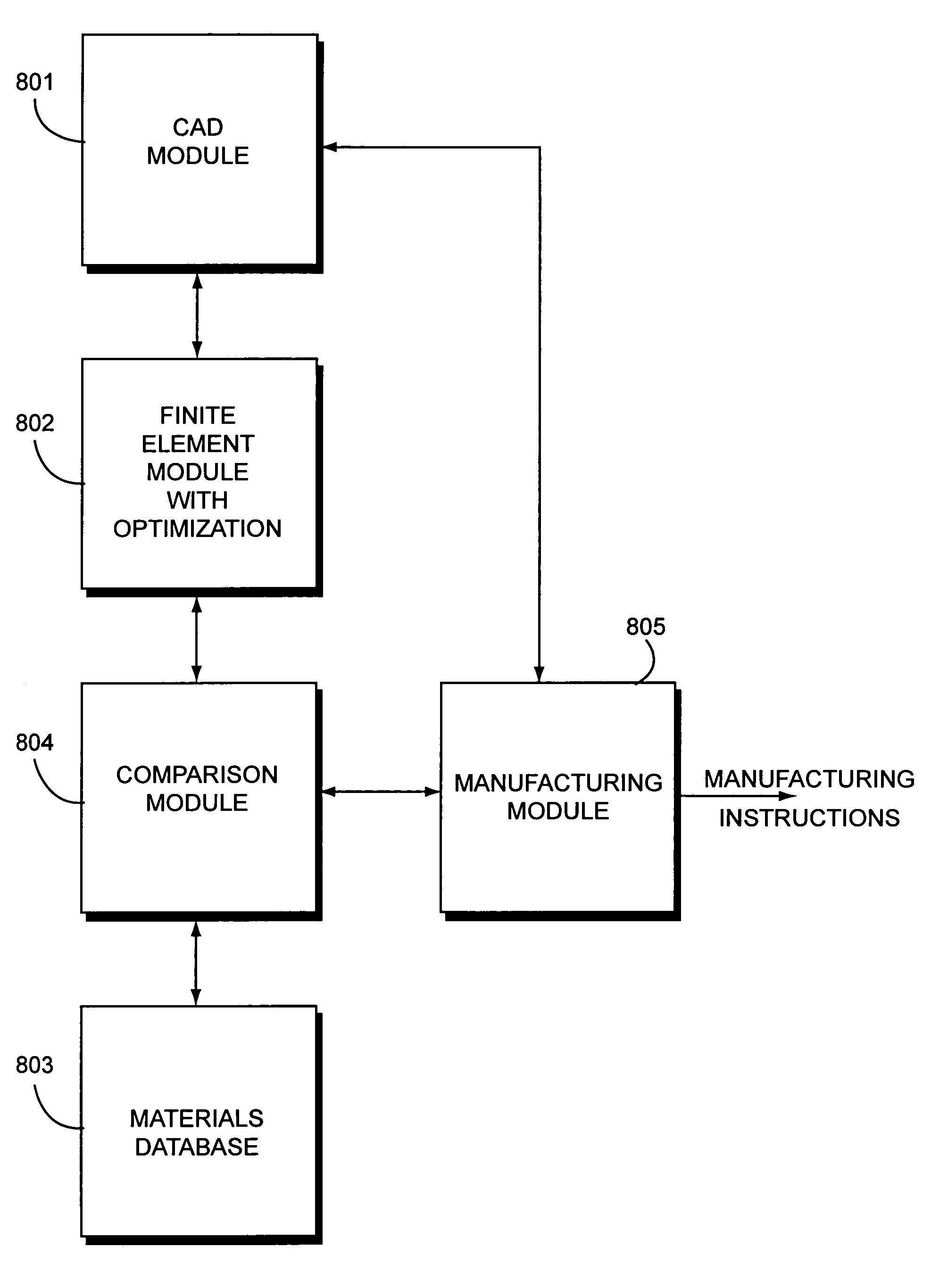
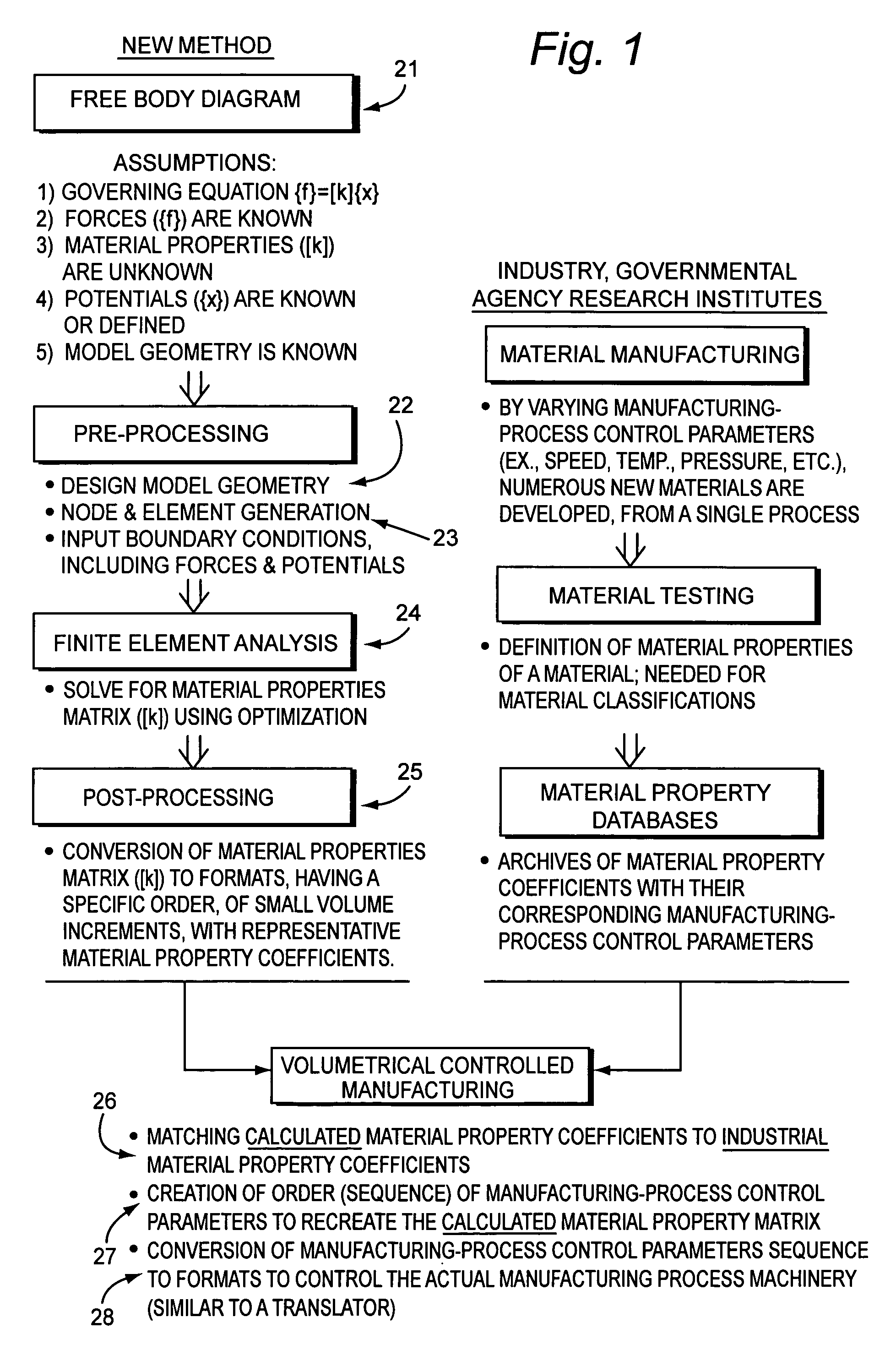
[0018]FIG. 1 will be used to describe a methodology for manufacturing an object or part in accordance with the present invention. As will become apparent from the description below, object or part (hereinafter “object”) as used herein refers to any object that may be manufactured by a process or technique in which manufacturing parameters may be controlled to vary constitutive or material properties within the object. The methodology for manufacturing an object in accordance with the instant invention is based on solutions of the equation

{f}=[k]{x}

where {f} represents a field that will be applied to the object in its intended use, {x} represents a potential corresponding to the applied field, and [k] represents the material properties of the object.

[0019]The methodology of the instant invention may be utilized with any manufacturing technique in which the manufacturing parameters may be varied. For example, a braiding process using a braider may be used to manufacture fiber composit...


PUM

PropertyMeasurementUnit
forcesaaaaaaaaaa
forceaaaaaaaaaa
Young's modulusaaaaaaaaaa

Abstract

A method for manufacturing an object having a potential {x} that is generated in response to a field {f} applied thereto. A computerized mathematical model of the object is generated by discretizing a geometric model of the object into a plurality of finite elements and specifying values for the field {f} and potential {x} relative to the finite elements. The material properties of the finite elements are specified to have a particular symmetry and a material property matrix [k] is calculated based on the relationship {f}=[k]{x} and the specified symmetry. Material property coefficients are extracted from the material property matrix [k] for each finite element in the computerized mathematical model and the extracted material property coefficients are compared to material property coefficients for known materials to match the extracted material property coefficients to the material property coefficients for known materials. Manufacturing parameters for controlling manufacturing equipment are determined based on the matched material property coefficients and the manufacturing equipment is controlled in accordance with the determined manufacturing parameters to thereby manufacture the object.

Description

RELATED APPLICATION[0001]This application claims priority from provisional Application No. 60 / 149,896, filed on Aug. 23, 1999, the contents of which are incorporated herein by reference.TECHNICAL FIELD[0002]The present invention generally relates to articles of manufacture and, more particularly, to a method and apparatus for manufacturing objects having response characteristics that are optimized for a desired application or use.BACKGROUND AND SUMMARY OF THE INVENTION[0003]Historically, analysis performed by engineers is one step in the long process in the attempt to simulate and verify real-world expected performance of engineered products. Complete models containing information such as geometry, material properties, loads and analysis type are entered into an analysis program and basic results such as displacements are calculated. These values can then be compared to predetermined limits of the material, whether isotropic, orthotropic, or anisotropic, to locate any critical areas...

Claims


Application Information

Patent Timeline
Patent Type & Authority Patents(United States)
IPC IPC(8): G06F17/50G06Q50/04A61F2/00A61F2/28A61F2/30A61F2/36A63B49/00A63B53/00A63B57/00G05B19/4097G05B19/418G05B19/42G06Q50/00
CPCA61F2/30942G06F17/5018A61F2/28A61F2/30965A61F2/36A61F2/3662A61F2002/30004A61F2002/30082A61F2002/30677A61F2002/30943A61F2002/30952A61F2002/30953A61F2002/30955A61F2002/30971A61F2002/3611A61F2210/0095A61F2250/0014A63B49/00A63B53/00A63B57/0075G05B2219/35017G05B2219/45168A63B57/207A63B57/353G06F30/23Y02P90/02G06Q50/04
Inventor ST. VILLE, JAMES A.
Owner AZTEC IP
Why Eureka
Try Eureka