Fireproof structure and installation method for protecting water pipes

a technology for installing methods and water pipes, which is applied in the direction of furniture, lighting and heating equipment, walls, etc., can solve the problems of high temperature and corrosive, water pipes can be directly exposed, and the durability of the resulting fireproof structure becomes unstable, so as to avoid the need and associated costs, and facilitate the water drainage

Inactive Publication Date: 2007-04-17
MITSUBISHI HEAVY IND LTD
View PDF20 Cites 8 Cited by
  • Summary
  • Abstract
  • Description
  • Claims
  • Application Information

AI Technical Summary

Benefits of technology

[0013]The present invention addresses the problems associated with the prior art. Its objective is to provide a fireproof structure for protecting water pipes and an installation method employing a fire proof structure which, even in the case where it falls off, does not leave the water pipes suddenly exposed, and even if the fireproof structure comes into contact with high temperature combustion gases, the fireproof structure assures protection for the water pipes and support members.

Problems solved by technology

However, the problem with the above described fireproof castable is that because it is of irregular dimensions, being coated or sprayed directly onto the walls of the water pipes, the durability of the resulting fireproof structure becomes unstable; after a few years, it tends to massively flake away or collapse.
With regard to the fireproof structure comprised of the externally formed and manufactured fireproof tiles described above, even though the tiles themselves have excellent durability, should any of them fall off, the water pipe can be directly exposed, and be damaged by the high temperatures and corrosive gasses.
In particular, when used in the stoker-type incinerators where the outlet temperatures can reach to an extremely high 1000° C., the difference between the thermal expansion of the support members for the fireproof structures using the foregoing fireproof castables or fireproof tiles, and that of the fireproof structure, causes cracks to form where combustion gases can invade and subsequently corrode the foregoing support members.
As a result, the foregoing fireproof structures are prone to separation and falling away, thereby allowing holes to form in the water piping.

Method used


Image

  • Fireproof structure and installation method for protecting water pipes
  • Fireproof structure and installation method for protecting water pipes
  • Fireproof structure and installation method for protecting water pipes

Examples


first embodiment

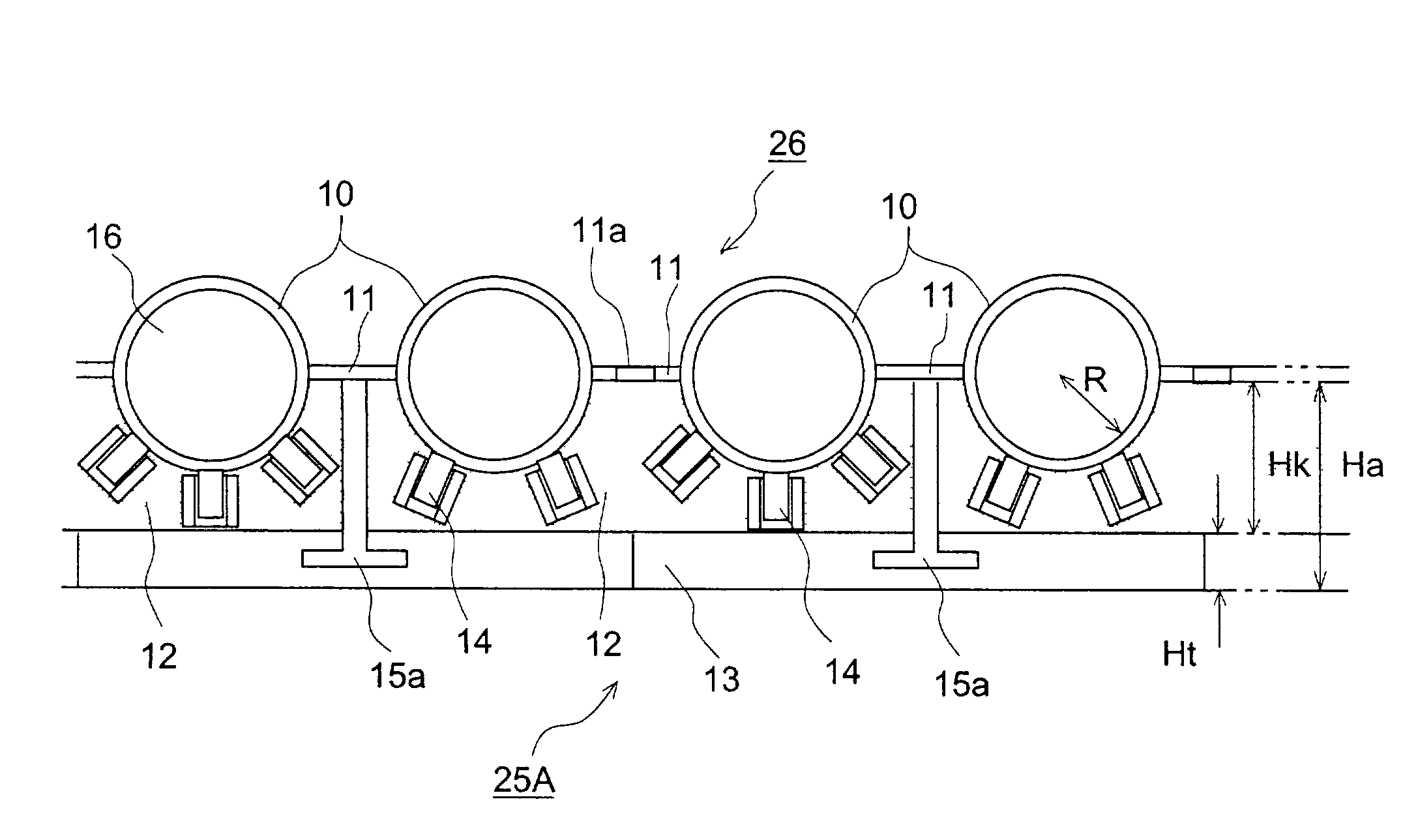
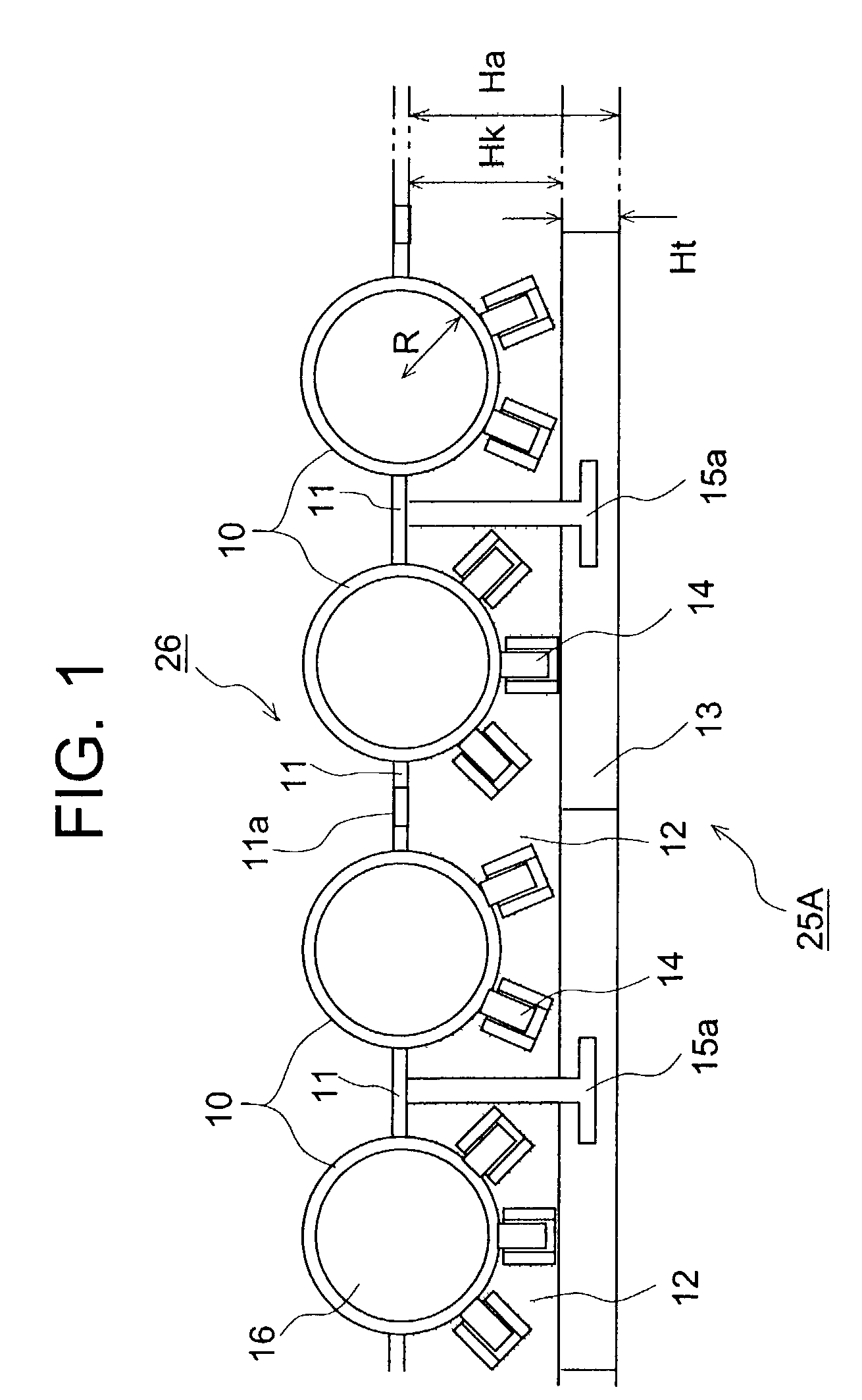
[0062]the fireproof structure 25A according to this invention, as shown in FIG. 1, employs a plurality of studs 14 in sets of two and three, projecting alternately from adjacent water pipes 10 at approximate 45 degree angles on the side where fireproof castable 12 is installed. This structural arrangement makes it very difficult for the fireproof castable 12 to fall off. It is preferable that the studs 14 be made from the same type of material as the water pipes to prevent studs 14 from causing damage due to having a different thermal expansion rate than water pipes 10. It is also desirable, as shown in FIG. 9, that the foregoing studs 14 be inserted into sleeves.

[0063]Further, stainless steel hanging hooks 15a have been welded to the foregoing fins 11 to hold the tiles in place. Also, as is shown for fireproof tiles 13 in FIG. 11, the tiles 13 may be held in place by using grooved tiles that engage the hanging hooks 15a.

[0064]Holes 11a have been pre-formed in the foregoing fins 11...

second embodiment

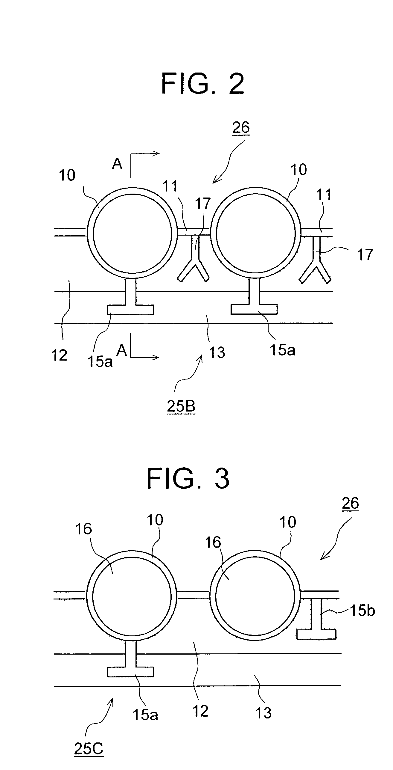
[0068]FIG. 4 is a cross sectional view of the second embodiment taken along line A—A of FIG. 2. 10 is the water pipes forming the coolant path 16, which are covered around their outside circumferences on the side facing the inside of the furnace by fireproof castable 12. Fireproof tiles 13 are installed atop that castable, and are held in place by hanging them onto L-shaped hanging hooks 15a and affixing with mortar 20.

[0069]FIG. 3 shows a third embodiment of fireproof structure 25C. The structure of this third embodiment is similar to those of the first and second embodiments, but the number of parts have been reduced by using the same L-shaped hooks for the tile hanging hooks 15a and for the castable support hooks 15b.

[0070]Since the fireproof structures in these embodiments are two-layered structures comprised of the foregoing fireproof castable 12 and fireproof tiles 13, should any of the fireproof tiles 13 facing the high temperature gas environment suddenly fall off, the fore...

fourth embodiment

[0073]FIG. 5 shows a fourth embodiment, where thermal spraying deposit has been used around the outside circumference of water pipes 10 in making a fireproof structure 25D. In this embodiment, water pipes 10 have been coated with thermal spraying deposit 18b, and then fireproof tiles 13 have been installed around the circumferences of that structure. The preferred thickness for thermal spraying deposit 18b would range from about 0.1 to 1.0 mm, and the material should be an alloy such as 50 Ni-50 Cr.

[0074]It would also be possible to use a cladding deposit other than the foregoing thermal spraying deposit 18b. In that case, the thickness of the structure should range from about 1 to 10 mm, and the material used for the build up should be a nickel based alloy such as Inconell.


PUM


Abstract

A fireproof structure protects water pipes with stable durability even in a high temperature gas environment. Even in a case where it falls off, it does not leave the water pipes suddenly exposed. The fireproof structure for protecting water pipes 25B installed on water pipe walls of a combustion gas side is configured by a double-layered structure made up of an outer layer water pipe protective structure facing towards the combustion gas side, which is fireproof tile 13, and an inner layer water pipe protective structure provided between the outer layer water pipe protective structure and the water pipes, which is fireproof castable 12. The thickness ratio between the castable 12 and the tiles 13 lies within the range of about 2:1 to 3:1, and the ratio between the thickness of the fireproof castable and the radius of the water pipe is set to 1+α:1, wherein the value of α ranges from approximately 0.1 to 0.3. The water pipes are equipped with hanging hooks 15a for tiles 13.

Description

BACKGROUND OF THE INVENTION[0001]1. Field of the Invention[0002]The present invention relates to a fireproof structure and installation method for water pipes used in heat exchangers in incinerators, boilers and the like which protects them in high temperature gas environments.[0003]2. Description of the Related Art[0004]Water pipes are installed inside of trash incinerators, boilers and the like to cool the high temperature gas environment or perform heat exchange. Those water pipes have been protected from not only the high temperature gas environment, but the abrasion from flying ash and corrosion, by the installation of fireproof tiles or fireproof castable structures around the inside of the furnace walls.[0005]Such conventional fireproof structures, as shown in FIG. 9, have studs 14 protruding from water pipes 10 on the combustion chamber side of the water pipe wall, in other words, the side in contact with the high temperature gases. Also employed are sleeves 19 embedded insi...

Claims


Application Information

Patent Timeline
Patent Type & Authority Patents(United States)
IPC IPC(8): F27D1/14F22B37/10
CPCF22B37/108
Inventor TERABE, YASUNORIINOUE, KEITANAKAGAWA, YUJISAEKI, KENTARO
Owner MITSUBISHI HEAVY IND LTD
Why Eureka
Try Eureka