

Cooking vessel grip and relative manufacturing method
a technology for cooking vessels and grips, applied in the direction of baking vessels, containers preventing decay, sealing, etc., can solve the problems of plastic material grips precisely in their solid state, prolonging the risk of burns to users
- Summary
- Abstract
- Description
- Claims
- Application Information
AI Technical Summary
Benefits of technology
Problems solved by technology
Method used
Image

Examples
Embodiment Construction
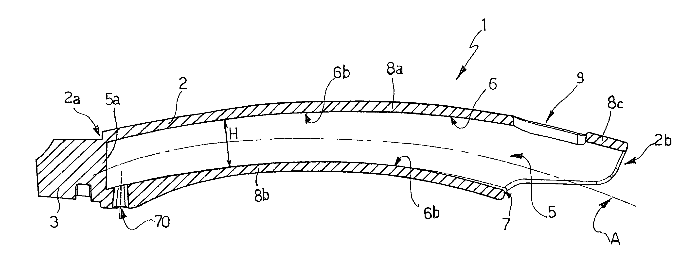
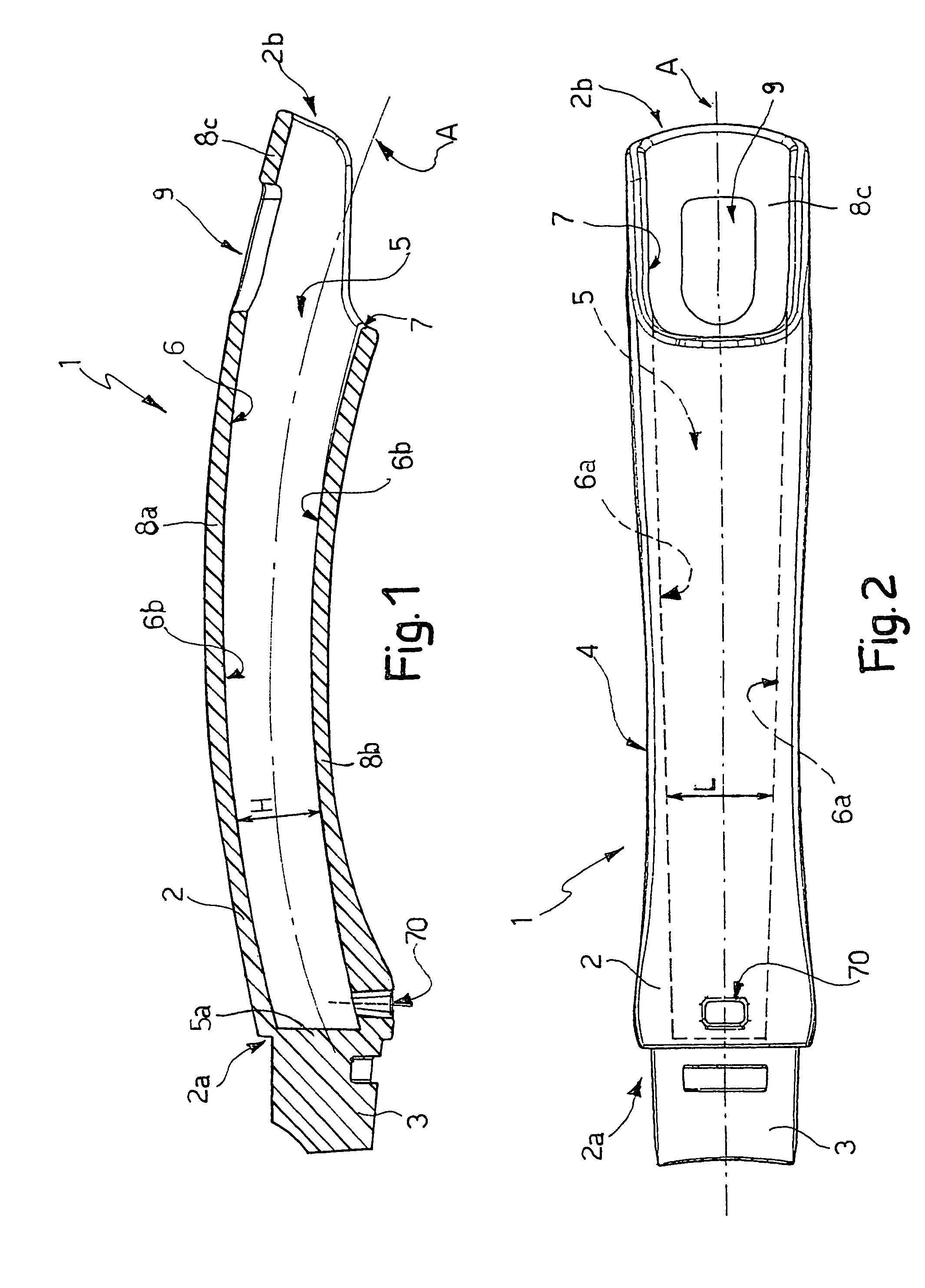
[0020]With reference to FIGS. 1 and 2, a cooking vessel grip, in particular a frying-pan handle, is indicated as a whole by 1, and comprises an elongated, one-piece body 2 molded from plastic material. Body 2 is preferably made of thermosetting polymer material, in particular a phenol-formaldehyde molding resin, such as Bakelite.
[0021]Body 2 is a hollow tubular body closed at one end, elongated longitudinally along an axis A, and having a longitudinally curved profile. More specifically, axis A is a curved central axis of symmetry of body 2.
[0022]A first end 2a of body 2 has means 3 of any known type for connection to a cooking vessel, such as a known frying-pan or saucepan not shown for the sake of simplicity. More specifically, a connecting portion 3, for connection in known manner to a cooking vessel, projects from first end 2a of body 2; and connection to the cooking vessel may be either fixed or reversible.
[0023]Body 2 also comprises a grip portion 4 gripped in use by the user ...
PUM
| Property | Measurement | Unit |
|---|---|---|
| length | aaaaa | aaaaa |
| shape | aaaaa | aaaaa |
| thermal insulation | aaaaa | aaaaa |
Abstract
Description
Claims
Application Information