Variable color landscape lighting

a landscape lighting and variable color technology, applied in lighting and heating equipment, lighting support devices, instruments, etc., can solve the problem of labor-intensive color control, and achieve the effect of rapid color chang

Inactive Publication Date: 2007-04-17
BEEMAN HLDG INC
View PDF5 Cites 21 Cited by
  • Summary
  • Abstract
  • Description
  • Claims
  • Application Information

AI Technical Summary

Benefits of technology

[0004]The methods and techniques disclose an electronically controlled landscape lighting system that uses multiple light emitting diode chips to provide rapid color change.
[0005]The systems and techniques described here may provide one or more of the following advantages. The light emitting diode chips can provide for long life of the illumination system when compared to incandescent systems. The light emitting diode sources have lower energy consumption than standard incandescent lighting systems with equivalent light output. An electronic controller may change the radiated color without changing bulbs or lenses. The lighting system can provide nearly instantaneous electronically controlled color-changing capability.

Problems solved by technology

Such color control is labor intensive and requires the storage and handling of numerous spare / replacement parts.

Method used


Image

  • Variable color landscape lighting
  • Variable color landscape lighting
  • Variable color landscape lighting

Examples


first embodiment

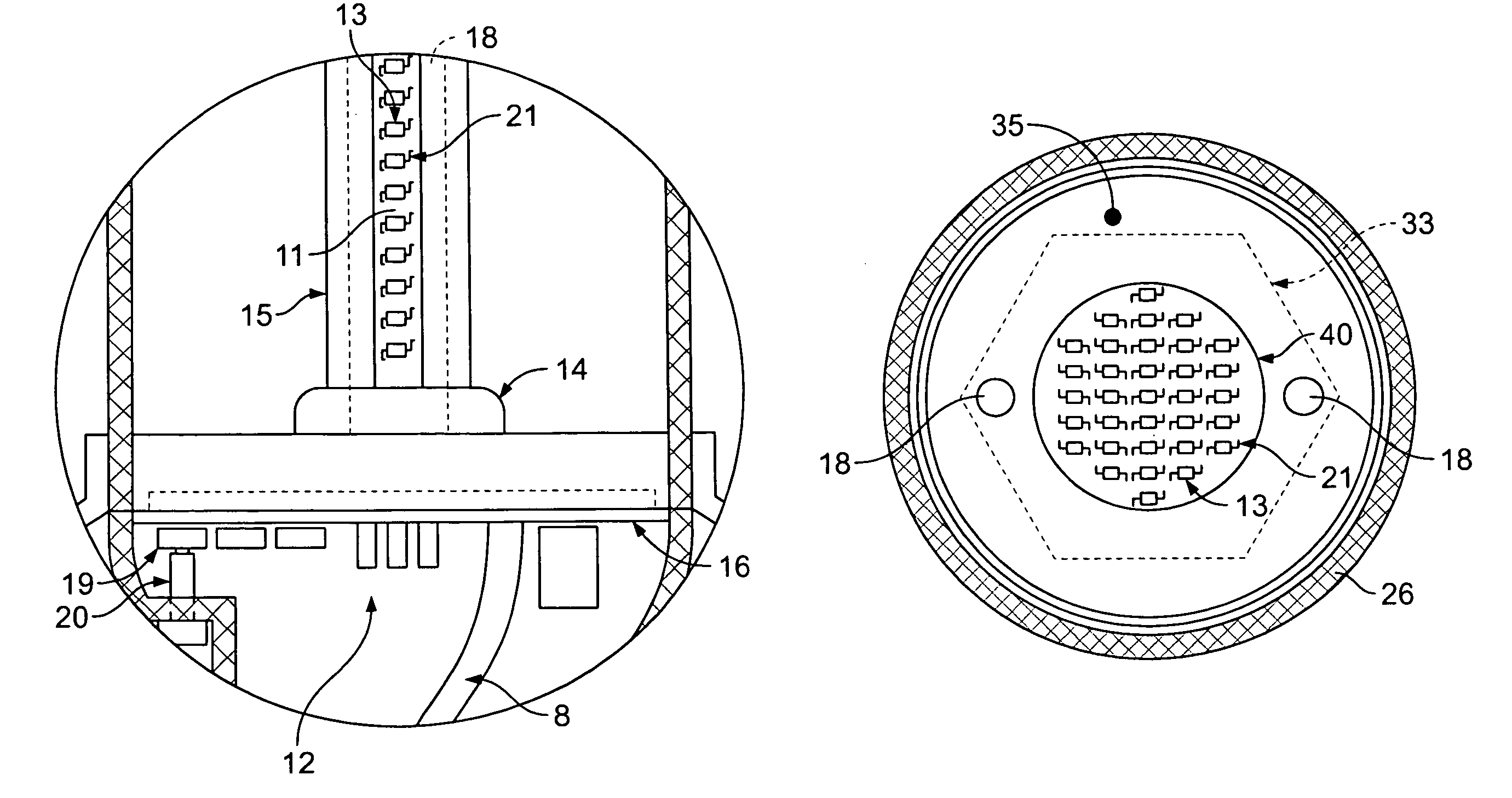
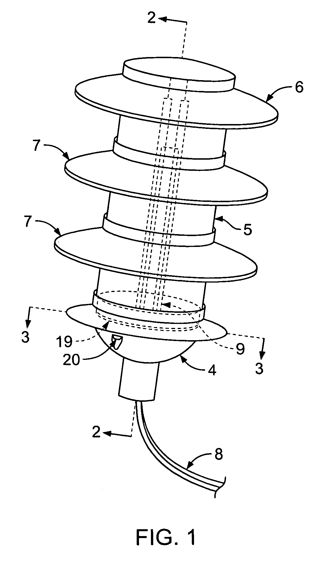
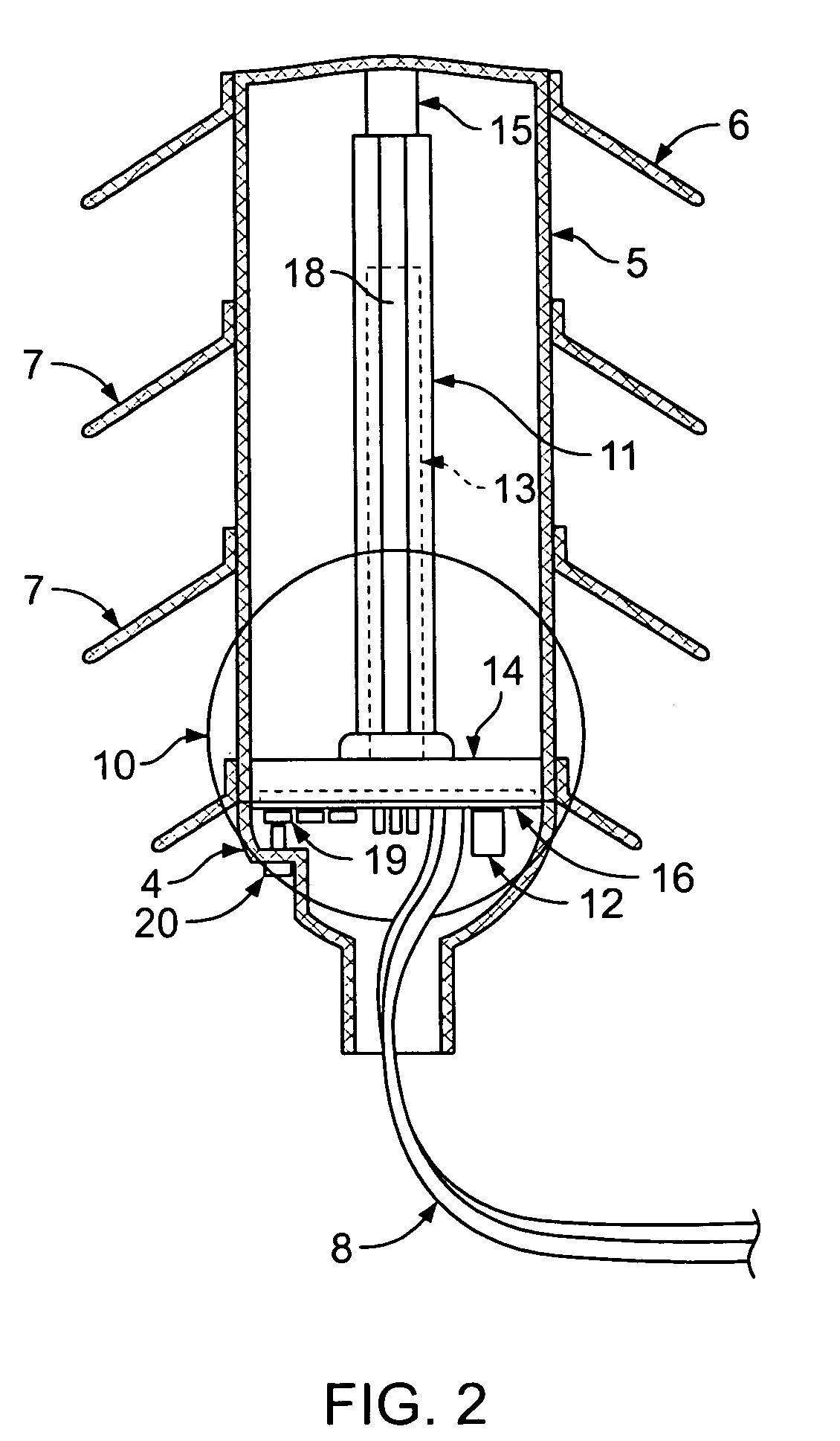
[0023]FIG. 3 shows the standard apparatus 9 of the present disclosure taken along the line 3—3 in FIG. 1, and details of a top view of standard apparatus 9, whereby the light emitting diode chips 13 are shown to be mounted on three evenly spaced-apart support members 11 and are covered with a transparent protection layer 17 that protects the light emitting diode chips 13 from physical damage. Although not limited thereto, protection layer is preferably made from a transparent silicone based material. FIG. 3 also shows metallic heat sink 15 being attached to connector 14 by means of a screw 18, although other mechanical connection means (not shown) are also contemplated for such attachment. FIG. 3 further shows lens 5 surrounding support members 11, heat sink 14, and connector 14 of standard apparatus 9, and lens 5 being supported upon base 4. Although three support members 11 are shown in FIG. 3, the number used is not critical and can vary from one to twelve, or even more, dependin...

third embodiment

[0031]FIG. 11 is an enlarged view of the circle 47 in FIG. 9 showing in detail standard apparatus 44 positioned within substantially rectangular housing 49 and having elongated substantially rectangular support member 54 in a longitudinally extending orientation relative to substantially rectangular housing 49, multiple light emitting diode chips 13 each mounted via whisker wires 21 to substantially rectangular support member 54, heat sink 59 positioned rearward from substantially rectangular support member 54, printed circuit board 16 positioned behind metallic heat sink 59, and reflector / refractor 50 positioned between printed circuit board 16 and heat sink 59, as well as a connector and wiring harness 36 providing the electrical connection to printed circuit board 16. The number of light emitting diode chips 13 held in place against substantially rectangular support member 54 is not critical and the present disclosure may comprise one or more light emitting diode chips 13. FIG. 1...


PUM


Abstract

A system of variable color landscape lights illuminated by multiple light emitting diode chips provides the user a controllable spectral output. In its various configurations, the electronic control system allows a selection of various spectral light radiation. The color output of the light emitting diode chips is electronically controlled and can be changed by means of a push button switch, radio frequency control, infrared control, signals impressed on line voltages, and other control system means.

Description

CROSS-REFERENCE TO RELATED APPLICATIONS[0001]This application claims the benefit of priority from U.S. Patent Application entitled “Electronically Controlled, Variable Color Landscape Lighting Using Multiple Light Emitting Diode Chips on a Printed Circuit Support Member,” filed Oct. 23, 2002, application Ser. No. 10 / 278,699, now abandoned, which is incorporated herein by reference in its entirety.BACKGROUND[0002]The present disclosure relates generally to lighting systems and more particularly to landscape lighting systems.[0003]Color enhancement of trees, planting beds, buildings, signage, driveways, sidewalks, landscaped paths, and the like may be desired for its aesthetically pleasing decorative effects and visual interest, as well as for seasonal accent. Red, white and blue colors may be favored for July 4th celebrations, red and green for end of the year holidays, pastels for Easter, and orange for Halloween. Also, as a replacement for glaring white light, when a choice is offe...

Claims


Application Information

Patent Timeline
Patent Type & Authority Patents(United States)
IPC IPC(8): F21V1/00F21S8/00F21V19/00F21V21/30F21V23/04F21V29/00H05B44/00
CPCF21V23/04F21V23/0435F21V29/004F21V29/89H05B33/0869F21V29/74F21V19/001F21V21/30F21W2131/109F21Y2101/02F21W2131/10F21Y2115/10H05B45/22
Inventor BEEMAN, RANDYCHISM, DAVID M.FERNALD, JR., DARRELL L.
Owner BEEMAN HLDG INC
Why Eureka
Try Eureka