
Laser mirror vision

a technology of mirrors and spherical mirrors, applied in image data processing, volume measurement apparatus/methods, liquid/fluent solid measurement, etc., can solve the problems of inaccurate volume estimation, high accuracy of three-dimensional image, so as to increase the efficiency of performance, reduce viewing angle, and increase the performance of capturing means

Inactive Publication Date: 2007-04-17
MAREL HF
View PDF7 Cites 73 Cited by
  • Summary
  • Abstract
  • Description
  • Claims
  • Application Information

AI Technical Summary

Benefits of technology

[0010]It is an object of the present invention to increase the accuracy in the determination of a three dimensional image of a moving object by means of additionally detecting the areas of the object which are not visible in the direct view.
[0021]In order to increase the efficiency in the performance in the capturing means, such as the resolution, at least one second side mirror could be situated between the at least one first side mirror and the at least one back rear mirror. In this embodiment the purpose of the at least one first side mirror is to reflect the laser beam underneath the side of the object towards the least one second side mirror. The at least one second side mirror would be positioned in such a way to decrease the viewing angle of the detecting means and therefore increase the performance in the capturing means. Instead of capturing the side view image from the at least one first side mirror, the side view image will be viewed in the at least one second side mirror and captured in the capturing means.
[0022]One embodiment of such arrangement is to use two first side mirrors and two second side mirrors with only one back rear window, wherein the distance between the two second side mirrors is shorter that between the first side mirrors which allows decreasing the viewing angle of the capturing means.

Problems solved by technology

The problem with the solution describe in U.S. Pat. No. 5,184,733 is how inaccurate it is.
By determining only the width and height of the object, the errors can be very height, especially when the object has irregular structure.
By measuring only the top view and the profile image the volume estimation can also be inaccurate, specially when the objects have a very irregular shape.
This causes an increase in uncertainty in the measurement.

Method used


Image

  • Laser mirror vision
  • Laser mirror vision
  • Laser mirror vision

Examples


Embodiment Construction

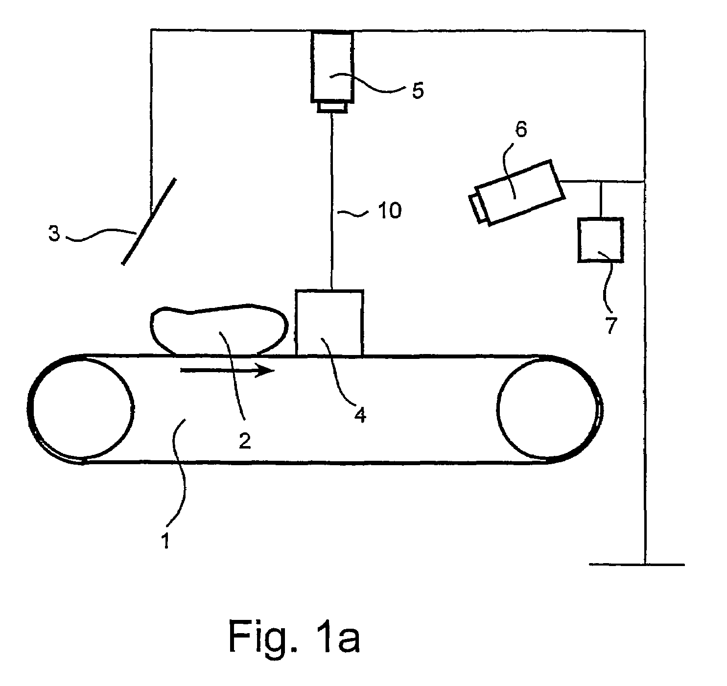
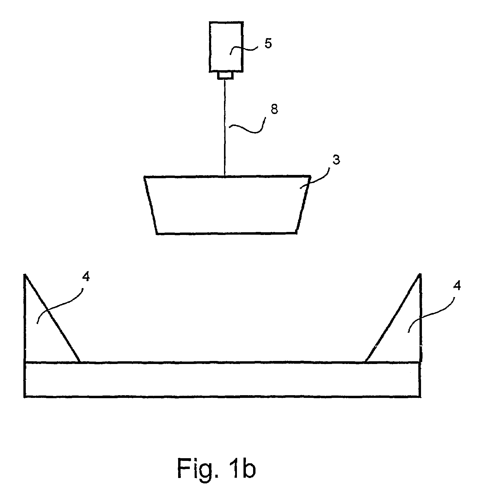
[0033]In the following the present invention, and in particular preferred embodiments thereof, will be described in greater details in connection with the accompanying drawings in which

[0034]FIG. 1a)–FIG. 1b) shows a perspective view of the apparatus according to the present invention,

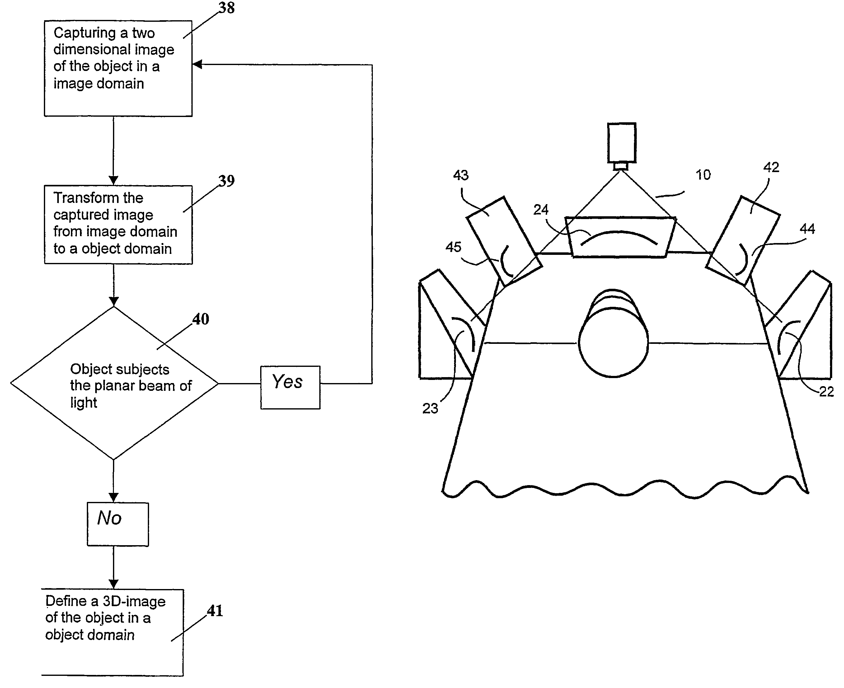
[0035]FIG. 2 shows an overview of the apparatus from the detecting means point of view wherein the object is a cylinder,

[0036]FIG. 3 shows image domains and transformation from the image domains to a mutual object domain for a cylinder,

[0037]FIG. 4 shows an overview of the apparatus from the detecting means point of view wherein the object is a cone shaped object,

[0038]FIG. 5 shows a image domains and transformation from the image domains to a mutual object domain for the cone shaped object,

[0039]FIG. 6 shows a overview of the cone shaped object,

[0040]FIGS. 7a) and 7b) shows two perspective views for a cone shaped object after repeating the image processing of the two dimensional image while the object...


PUM


Abstract

The present invention relates to a method and an apparatus for determining a three dimensional image of the a moving object by means of reflecting means such as mirrors and a planar beam of light such as a laser light. As the object enters the light a two dimensional image of the object is captured, wherein the image comprises both the reflection of the beam of light from the object and also the reflection from the reflecting means. By transformation procedure a two dimensional image is transformed to a two dimensional object image and based on plurality of such images a three dimensional image is defined from which the volume can be calculated. This can be used to determine the weight distribution of the object, which is important for portioning.

Description

[0001]This application is the U.S. national phase of international application PCT / IS02 / 00004 filed 1 Feb. 2002, which designated the U.S.[0002]This application also claims the benefit of the filing date of U.S. provisional patent application Ser. No. 60 / 265,876, filed 5 Feb. 2001.FIELD OF THE INVENTION[0003]The present invention relates to a method and an apparatus for determining a three dimensional image of the a moving object by means of reflecting means such as mirrors and a planar beam of light such as a laser light.DESCRIPTION OF THE PRIOR ART[0004]Determination of a three dimensional image of conveyed food items is an important task for the food industry. When the processing comprises grading objects by form, size and weight, information regarding the volume and the shape of the food item is necessary.[0005]U.S. Pat. No. 5,184,733 describes a method and apparatus for determining the volume, form and weight of objects. A linescan camera records a top view of the object and at...

Claims


Application Information

Patent Timeline
IPC IPC(8): G01B11/14G01B11/22G01N21/00G01B11/00G01B11/25G01F17/00G06K9/00G06T7/00H04N13/00
CPCG01B11/00G01B11/25G01B11/2545G01F17/00G06K9/00201G06T7/0065H04N13/0217G06T7/55H04N13/218G06V20/64
Inventor ANDERSEN, KRISTINNHALLVARDSSON, KRISTIANNARFASON, SIGURBJORNERLINGSSON, VIDAR
Owner MAREL HF
Features
  • Generate Ideas
  • Intellectual Property
  • Life Sciences
  • Materials
  • Tech Scout
  • Unparalleled Data Quality
  • Higher Quality Content
  • 60% Fewer Hallucinations
Learn More