Cooling apparatus

a technology of cooling apparatus and detector, which is applied in the direction of lighting and heating apparatus, fluid pressure control, instruments, etc., can solve the problems of reducing the maximum cooling capacity that can ultimately be realized, and achieve the effects of improving heat transfer, improving thermal insulation, and shortening cooling tim

Inactive Publication Date: 2007-04-17
DIEHL BGT DEFENCE GMBH & CO KG
View PDF10 Cites 5 Cited by
  • Summary
  • Abstract
  • Description
  • Claims
  • Application Information

AI Technical Summary

Benefits of technology

[0014]The invention is based on the consideration that an outer countercurrent heat exchanger for a second gas, as a result of the provision of an inner countercurrent heat exchanger which is spatially separated from the outer one by an outer sleeve, is subjected to a thermal load at the moment at which the second gas has been cooled to below the temperature of the first gas of the inner countercurrent heat exchanger. This reduces the maximum cooling capacity which can ultimately be realized.
[0034]Furthermore, it is advantageous for the countercurrent heat exchangers to comprise a tube which is provided with fins and around which plastic filaments are drawn. The plastic filaments, like the fins, serve to further improve the heat transfer through diversion of gases. The resultant improvement in the heat transfer leads to shorter cooling times and therefore to the detector being ready for operation more quickly. Furthermore, it is in this way possible to improve the cooling capacity by reaching lower temperatures for the gas of the outer countercurrent heat exchanger. This also allows operation of detectors with a large surface area.

Problems solved by technology

This reduces the maximum cooling capacity which can ultimately be realized.

Method used


Image

  • Cooling apparatus
  • Cooling apparatus

Examples


Embodiment Construction

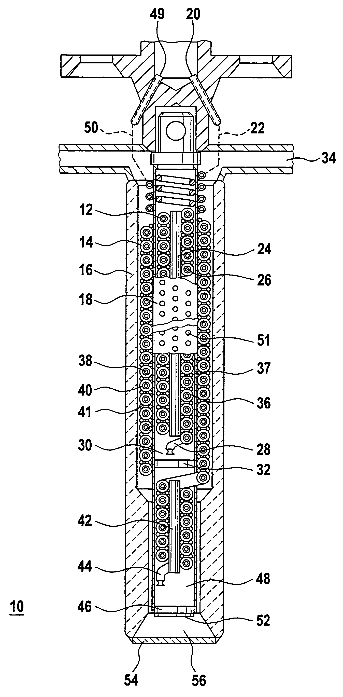
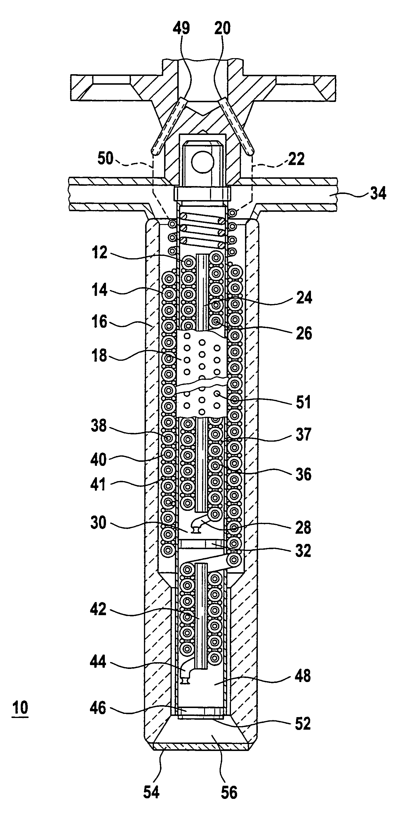
[0036]The cooling apparatus 10 has an inner countercurrent heat exchanger 12 and an outer countercurrent heat exchanger 14. The two countercurrent heat exchangers 12, 14 are arranged in a thermally insulating housing 16. The inner countercurrent heat exchanger 12, the outer countercurrent heat exchanger 14 and the housing 16 are positioned concentrically with respect to one another. The inner countercurrent heat exchanger 12 is spatially separated from the outer countercurrent heat exchanger 14 by a thin metallic outer sleeve 18.

[0037]A first high-pressure gas flows out of a pressure vessel (not shown) into the inner countercurrent heat exchanger 12 via a gas connection 20 and a feed line 22. The first high-pressure gas flows through a tube 26 arranged helically around an inner sleeve 24 of poor thermal conductivity until it reaches an expansion nozzle 28 located at the end of the tube 26. The first high-pressure gas is expanded at the expansion nozzle 28 and as a result is cooled i...


PUM


Abstract

A cooling apparatus (10) for cooling a detector (52), the cooling apparatus including an inner and an outer countercurrent heat exchanger (12 and 14, respectively) for a first and a second gas in a thermally insulating housing (16), the inner countercurrent heat exchanger (12) being arranged within a sublength of the outer countercurrent heat exchanger (14), and the inner countercurrent heat exchanger (12) being spatially separated from the outer countercurrent heat exchanger (14) by an outer sleeve (18). In this apparatus, the outer sleeve (18) has a partition plate (32) between an expansion nozzle (28) for the first gas located at the end of the inner countercurrent heat exchanger (12) and the remaining part of the outer countercurrent heat exchanger (14).

Description

BACKGROUND OF THE INVENTION[0001]1. Field of the Invention[0002]The invention relates to a cooling apparatus for a detector wherein the cooling apparatus includes an inner and an outer countercurrent heat exchanger for a first and second gas in a thermally insulating housing, whereby the inner countercurrent heat exchanger is arranged within a sublength of the outer countercurrent heat exchanger is spatially separated from the outer countercurrent heat exchanger by an outer sleeve.[0003]Detectors, such as for example semiconductor detectors, only reach their optimum radiation sensitivity at temperatures well below room temperature. It is therefore necessary to cool the detectors.[0004]2. Discussion of the Prior Art[0005]EP 0 432 583 B1 has disclosed a cooling apparatus for cooling an object, the apparatus being composed of two series-connected coolers for two different gases. The first cooler for a first gas is a countercurrent heat exchanger which has an expansion nozzle located be...

Claims


Application Information

Patent Timeline
Patent Type & Authority Patents(United States)
IPC IPC(8): H01J5/02F25B41/00F28D7/02F28D7/12G05D16/00G05D23/00F25B9/02
CPCF25B9/02F25B2309/023F25B9/10F25B19/005F25B19/02F25D3/10H01L23/467
Inventor HINGST, UWE
Owner DIEHL BGT DEFENCE GMBH & CO KG
Why Eureka
Try Eureka