Electronic device cooling assembly and method employing elastic support material holding a plurality of thermally conductive pins

a technology of elastic support material and thermally conductive pins, which is applied in the direction of power cables, cables, semiconductor/solid-state device details, etc., can solve the problems of additional chip processing that is deemed undesirable, risking the loss of expensive functional chips, and plugged orifices, etc., to facilitate thermal interfacing of pins, facilitate physical contact, and facilitate the planar surface

Inactive Publication Date: 2007-04-17
INT BUSINESS MASCH CORP
View PDF15 Cites 48 Cited by
  • Summary
  • Abstract
  • Description
  • Claims
  • Application Information

AI Technical Summary

Benefits of technology

[0008]Therefore, a need exists for a practical cooling assembly and method which allows for high heat transfer from a surface of an electronic device to be cooled using a direct liquid coolant impingment approach, without using structures likely to be obstructed by debris in the system.
[0009]This need is met and additional advantages are provided through a cooling assembly for an electronic device. The cooling assembly includes a manifold having at least one orifice therein for injecting a cooling liquid onto a surface to be cooled, and an elastic pin support material. The surface to be cooled comprises either a surface of the electronic device or a surface in thermal contact with the electronic device. The elastic pin support material has at least one opening aligned to the at least one orifice of the manifold for allowing the cooling liquid to pass therethrough. A plurality of thermally conductive pins are mounted within the elastic pin support material and extend therefrom. The plurality of thermally conductive pins are sized to physically contact the surface to be cooled when the cooling assembly is employed to cool the electronic device, and include first ends embedded within the elastic pin support material. The elastic pin support material has a thickness and compliance which facilitates physical contact of the plurality of thermally conductive pins to the surface to be cooled by allowing second ends thereof to move vertically and tilt. The second end of each thermally conductive pin comprises a planar surface which is normal to an axis of the thermally conductive pin. When the cooling assembly is employed to cool the electronic device, the elastic pin support material facilitates the planar surfaces of the second ends of the pins establishing planar contact with the surface to be cooled, notwithstanding that the surface may be other than planar.
[0010]In another aspect, an electronic module is provided which includes a substrate having at least one electronic device to be cooled disposed thereon. A cooling assembly is provided for the at least one electronic device. This cooling assembly includes a manifold having at least one orifice therein for injecting a cooling liquid onto a surface to be cooled and an elastic pin support material. The surface to be cooled comprises either a surface of the electronic device or a surface in thermal contact with the electronic device. The elastic pin support material has an opening aligned to the orifice of the manifold for allowing the cooling liquid to pass therethrough. A plurality of thermally conductive pins are mounted within the support material and extend therefrom. The pins physically contact the surface to be cooled and include first ends embedded within the support material. The support material has a thickness and compliance which facilitates thermal interfacing of the pins to the surface to be cooled by allowing second ends thereof to move vertically and tilt. The second end of each thermally conductive pin has a planar surface which is normal to an axis of the thermally conductive pin. The elastic pin support material facilitates the planar surfaces of the second ends of the plurality of thermally conductive pins being in planar contact with the surface to be cooled, notwithstanding that the surface may be other than planar.
[0011]In a further aspect, a method of fabricating a cooling assembly for an electronic device is provided. The method includes providing a manifold having at least one orifice for injecting a cooling liquid onto a surface to be cooled, the surface comprising either a surface of the electronic device or a surface in thermal contact with the electronic device; and providing an elastic pin support material having a plurality of thermally conductive pins mounted therein and extending therefrom, the support material having an opening aligned to the orifice of the manifold for allowing the cooling liquid to pass therethrough. The conductive pins are sized to physically contact the surface to be cooled when the cooling assembly is employed to cool the electronic device. The support material has a thickness and compliance which facilitates thermal interfacing of the pins to the surface to be cooled by allowing second ends of the pins to move vertically and tilt. The second end of each thermally conductive pin comprises a planar surface which is normal to an axis of the thermally conductive pin. The elastic pin support material facilitates the planar surfaces of the second ends establishing planar contact with the surface to be cooled, notwithstanding that the surface may be other than planar.

Problems solved by technology

A concern with such small orifices is that they may act to filter debris in the system, resulting in the orifices becoming plugged.
Both require additional chip processing that is deemed undesirable in terms of risking the loss of expensive functional chips.

Method used


Image

  • Electronic device cooling assembly and method employing elastic support material holding a plurality of thermally conductive pins
  • Electronic device cooling assembly and method employing elastic support material holding a plurality of thermally conductive pins
  • Electronic device cooling assembly and method employing elastic support material holding a plurality of thermally conductive pins

Examples


Embodiment Construction

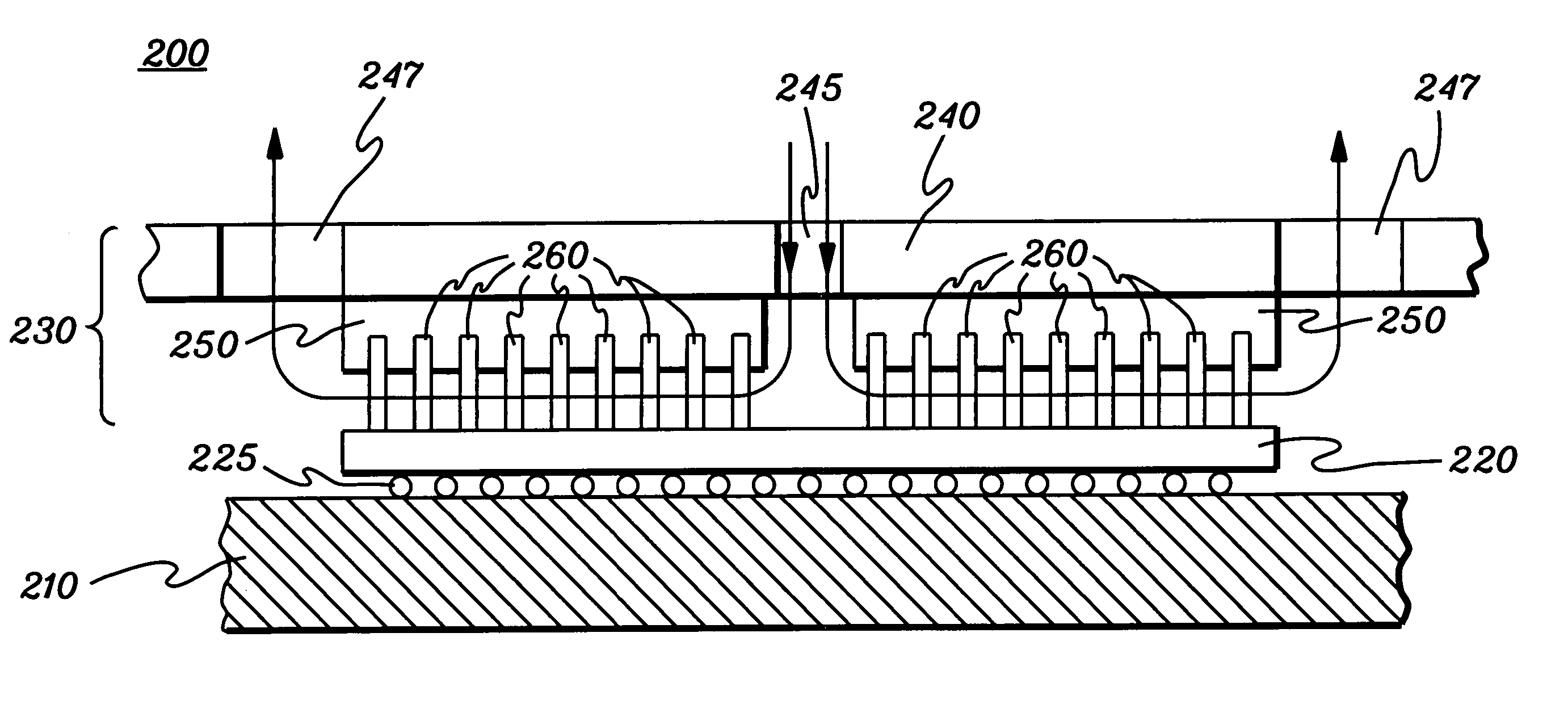
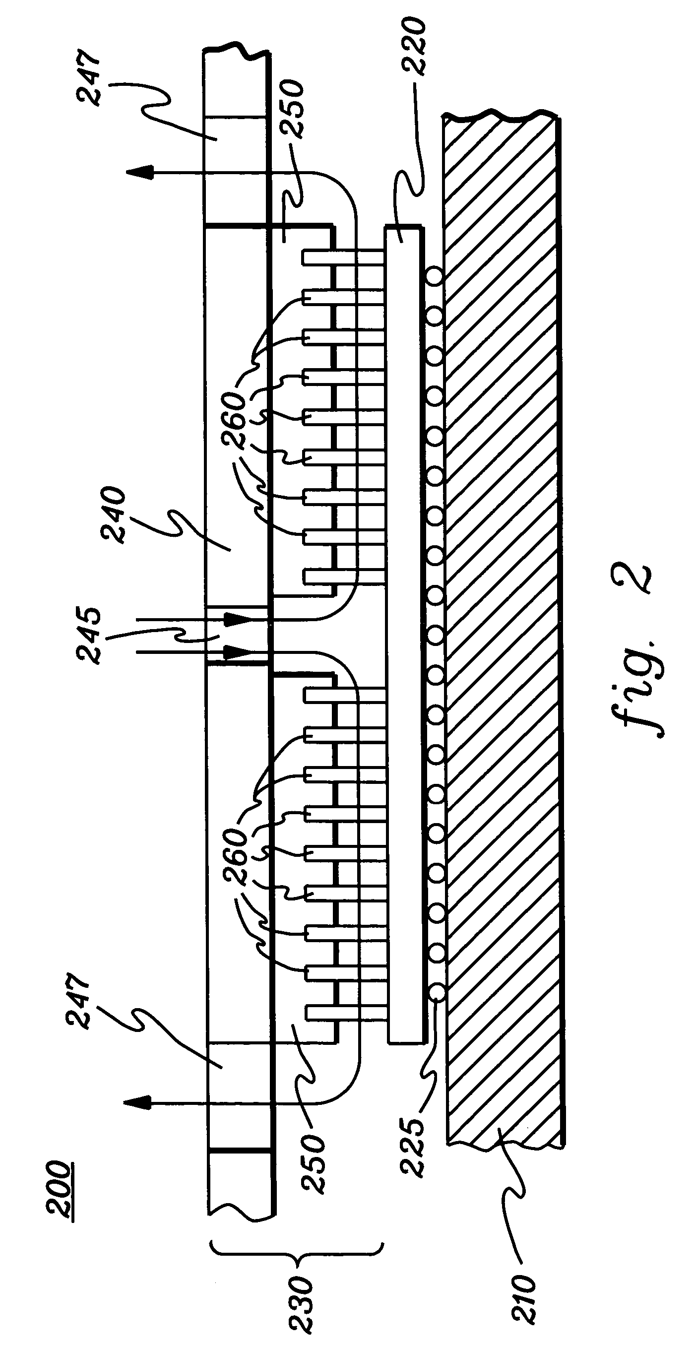
[0021]Generally stated, provided herein is an enhanced cooling assembly and method which allows for high heat transfer from a surface in thermal contact with an electronic device to be cooled using a direct liquid coolant impinging approach. In one embodiment, the cooling liquid is assumed to comprise a water-based fluid, and the cooling assembly is employed in combination with a passivated electronic substrate assembly. Other cooling liquids could be employed, however.

[0022]The cooling assembly employs an elastic (i.e., low modulus of elasticity) pin support material, such as an elastomeric material or rubber-based material, to compliantly hold a plurality of thermally conductive pins. The plurality of thermally conductive pins are mounted within the support material and have second ends extending therefrom. The pins are sized to physically contact a surface to be cooled. The surface to be cooled can comprise either a surface of an electronic device itself, or a surface thermally c...


PUM


Abstract

An electronic device cooling assembly and fabrication method are provided which include a manifold with an orifice for injecting a cooling liquid onto a surface to be cooled, and an elastic pin support material with an opening aligned to the orifice of the manifold. Multiple thermally conductive pins are mounted within the support material, extending therefrom, and are sized to physically contact the surface to be cooled. The support material has a thickness and compliance which facilitates thermal interfacing of the pins to the surface by allowing second ends thereof to move vertically and tilt. The second end of each pin has a planar surface which is normal to an axis of the pin, and the support material facilitates the planar surfaces of the second pin ends establishing planar contact with the surface to be cooled, notwithstanding that the surface may be other than planar.

Description

CROSS REFERENCE TO RELATED APPLICATION[0001]This application contains subject matter which is related to the subject matter of the following application, which is assigned to the same assignee as this application and which is hereby incorporated herein by reference in its entirety:[0002]“Electronic Device Substrate Assembly With Multilayer Impermeable Barrier And Method Of Making”, Chu et al., Ser. No. 10 / 197,661, filed Jul. 17, 2002.FIELD OF THE INVENTION[0003]The present invention relates to heat transfer mechanisms, and more particularly, to heat transfer mechanisms and cooling assemblies for removing heat generated by an electronic device, and to methods of constructing such cooling assemblies. More particularly, the present invention relates to cooling assemblies with an elastic layer supporting a plurality of thermally conductive pins capable of vertical and tilt movements for facilitating physical, planar coupling of planar ends of the plurality of thermally conductive pins w...

Claims


Application Information

Patent Timeline
Patent Type & Authority Patents(United States)
IPC IPC(8): H05K7/20F28F7/00H01L23/34H02G3/03H01L23/433
CPCH01L23/4336H01L2924/09701H01L2924/0002H01L2924/00
Inventor CAMPBELL, LEVI A.CHU, RICHARD C.ELLSWORTH, JR., MICHAEL J.IYENGAR, MADHUSUDAN K.SIMONS, ROBERT E.SCHMIDT, ROGER R.
Owner INT BUSINESS MASCH CORP
Why Eureka
Try Eureka