
Apparatus and method for measuring the dispersion of a fiber span

a fiber span and apparatus technology, applied in the field of optical communication, can solve the problems of long measurement time, large size and cost of tunable laser sources, and measurement accuracy not being accurate enough, and achieve the effect of high accuracy

Inactive Publication Date: 2007-04-17
XYLON LLC
View PDF88 Cites 14 Cited by
  • Summary
  • Abstract
  • Description
  • Claims
  • Application Information

AI Technical Summary

Benefits of technology

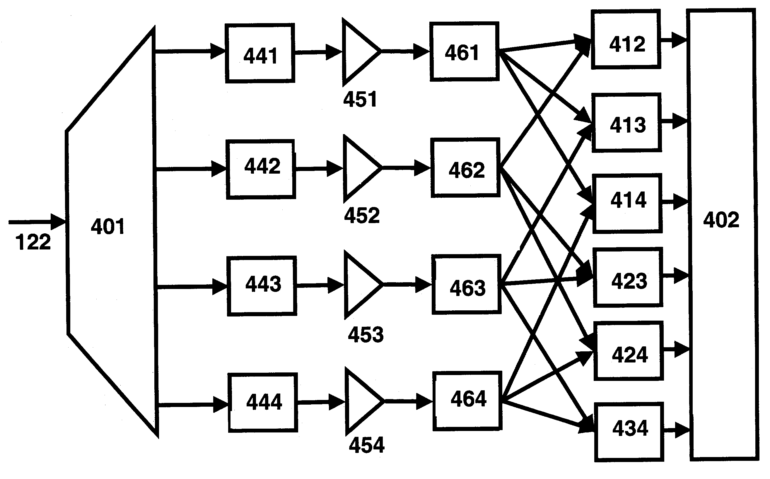
[0010]In the present invention, a dispersion measurement technique is taught to measure the dispersion of a fiber span at a si

Problems solved by technology

In addition to the need for a tunable source, this method suffers from error introduced by the finite spectral width of the tunable source.
These limitations prevent the measurement from being accurate enough for optical transport systems with trans-continental reaches.
Another drawback of this technique is the large size and cost of the tunable laser source.
Yet another limitation of this technique is the long measurement time that the method takes, mainly due to the tuning of the laser source or the tunable filter / monochromator.
This long time is both inconvenient and increases the errors because of equipment drift.

Method used


Image

  • Apparatus and method for measuring the dispersion of a fiber span
  • Apparatus and method for measuring the dispersion of a fiber span
  • Apparatus and method for measuring the dispersion of a fiber span

Examples


Embodiment Construction

[0020]While the making and using of various embodiments of the present invention are discussed in detail below, it should be appreciated that the present invention provides many applicable inventive concepts which can be embodied in a wide variety of specific contexts. The specific embodiments described herein are merely illustrative of specific ways to make and use the invention and do not delimit the scope of the invention.

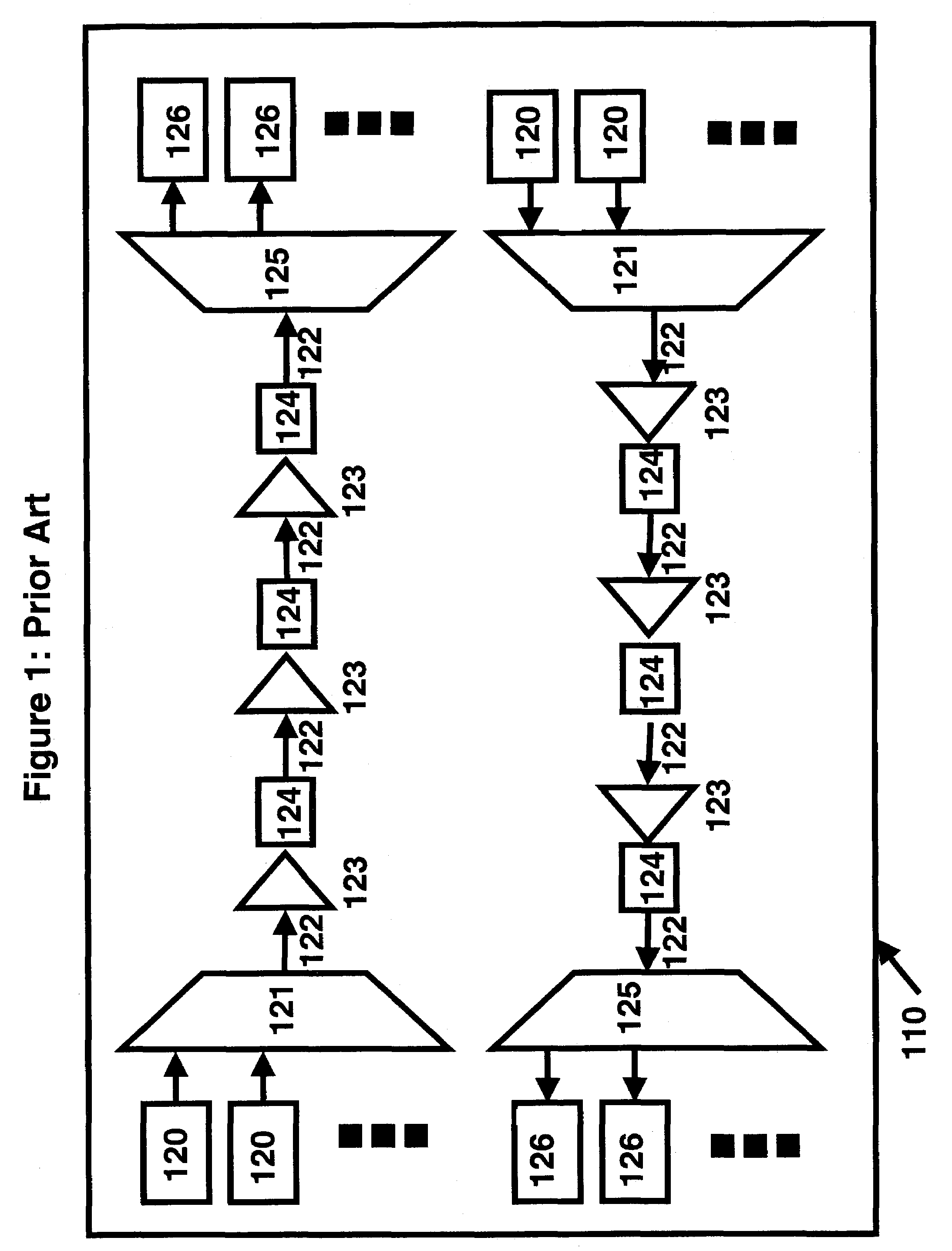
[0021]FIG. 1 is an illustrative block diagram of a prior art optical transport system 110 for data and / or voice transmission used to support the present invention. Typical long haul optical transport dense wavelength division multiplexed (DWDM) systems transmit 40 to 80 10 Gbps (gigabit per second) channels across distances of 3000 to 6000 km in a single 30 nm spectral band. Shown in the figure is a duplex system in which traffic is both transmitted and received between parties at opposite end of the link. The optical carrier is generated using transmitters 120....


PUM


Abstract

The invention pertains to optical fiber transmission systems, and is particularly relevant to transmission of large volumes of data over long distances at high rates. An improved apparatus and method for measuring dispersion in a fiber span is disclosed. In particular, the invention teaches a highly accurate technique for measuring the fiber dispersion at a single wavelength. Transmitter and receiver structure and data processing algorithms are disclosed. An improved apparatus and method for measuring dispersion in a fiber span. In particular, the invention teaches a highly accurate technique for measuring the fiber dispersion at a single wavelength. Transmitter and receiver structure and data processing algorithms are disclosed.

Description

CROSS-REFERENCE TO RELATED APPLICATION[0001]This application claims priority to U.S. Provisional Patent Application Ser. No. 60 / 377,083, entitled “METHOD FOR DISPERSION MEASUREMENT OF AN OPTICAL FIBER AT A FIXED WAVELENGTH”, by Michael H. Eiselt, filed Apr. 30, 2002.TECHNICAL FIELD OF THE INVENTION[0002]The present invention relates, in general, to the field of optical communications, and in particular to, an improved apparatus and method for measuring dispersion in a fiber span. In particular, the invention teaches a highly accurate technique for measuring the fiber dispersion at a single wavelength. Transmitter and receiver structure and data processing algorithms are disclosed.BACKGROUND OF THE INVENTION[0003]A goal of many modern long haul optical transport systems is to provide for the efficient transmission of large volumes of voice traffic and data traffic over trans-continental distances at low costs. Various methods of achieving these goals include time division multiplexin...

Claims


Application Information

Patent Timeline
IPC IPC(8): H04B10/12H04B10/18
CPCH04B10/2513
Inventor EISELT, MICHAEL H.
Owner XYLON LLC
Learn More