Universal rotary device for marking an article with ink

a technology of ink-based marking and rotary device, which is applied in the field of tattooing, can solve the problems of high noise, inability to use in operating rooms or other environments, and visible sparking contacts of breakers, and achieves the effects of easy to achieve, little familiarization or training, and rapid acclimation to the devi

Inactive Publication Date: 2007-04-24
DAIGLE RONALD
View PDF5 Cites 52 Cited by
  • Summary
  • Abstract
  • Description
  • Claims
  • Application Information

AI Technical Summary

Benefits of technology

[0007]A marking device according to the present invention utilizes an open framed design allowing easy access to all components for adjustment, maintenance and repair. The opened framed design exposes the operator to the operation of the machine and relationships between parts and components. This allows the operator to become quickly acclimated to its operation with little familiarization or training. Operation is intuitive and and acclimation to the device is rapid. The device is designed to utilize commercially available parts that are readily available from local supply stores, internet suppliers, and mail order catalog stores. Referring to FIG. ...

Problems solved by technology

The make-and-break units have visible sparking contacts and produce a high degree of noise when in use.
Because of the spar...

Method used


Image

  • Universal rotary device for marking an article with ink
  • Universal rotary device for marking an article with ink
  • Universal rotary device for marking an article with ink

Examples


Embodiment Construction

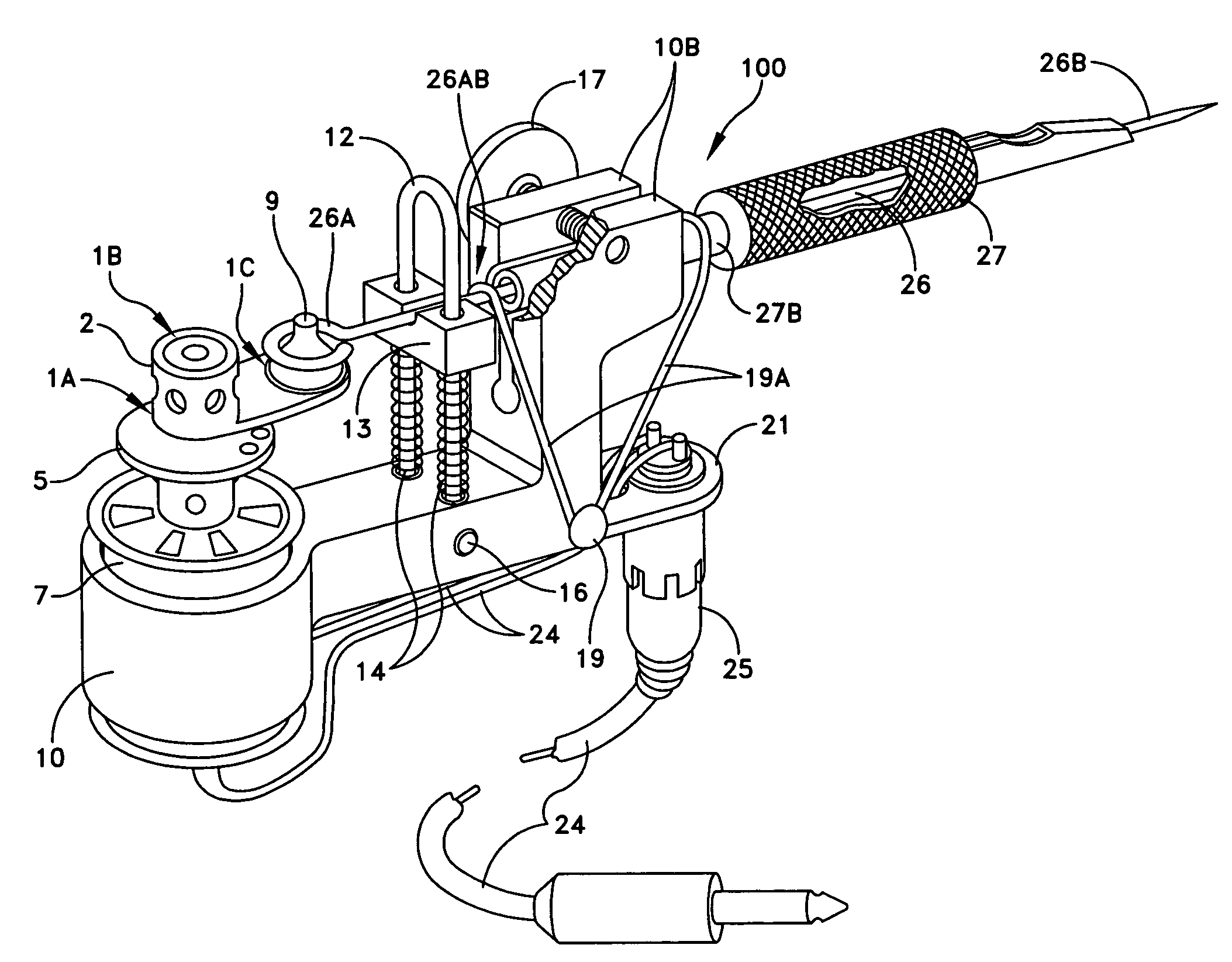
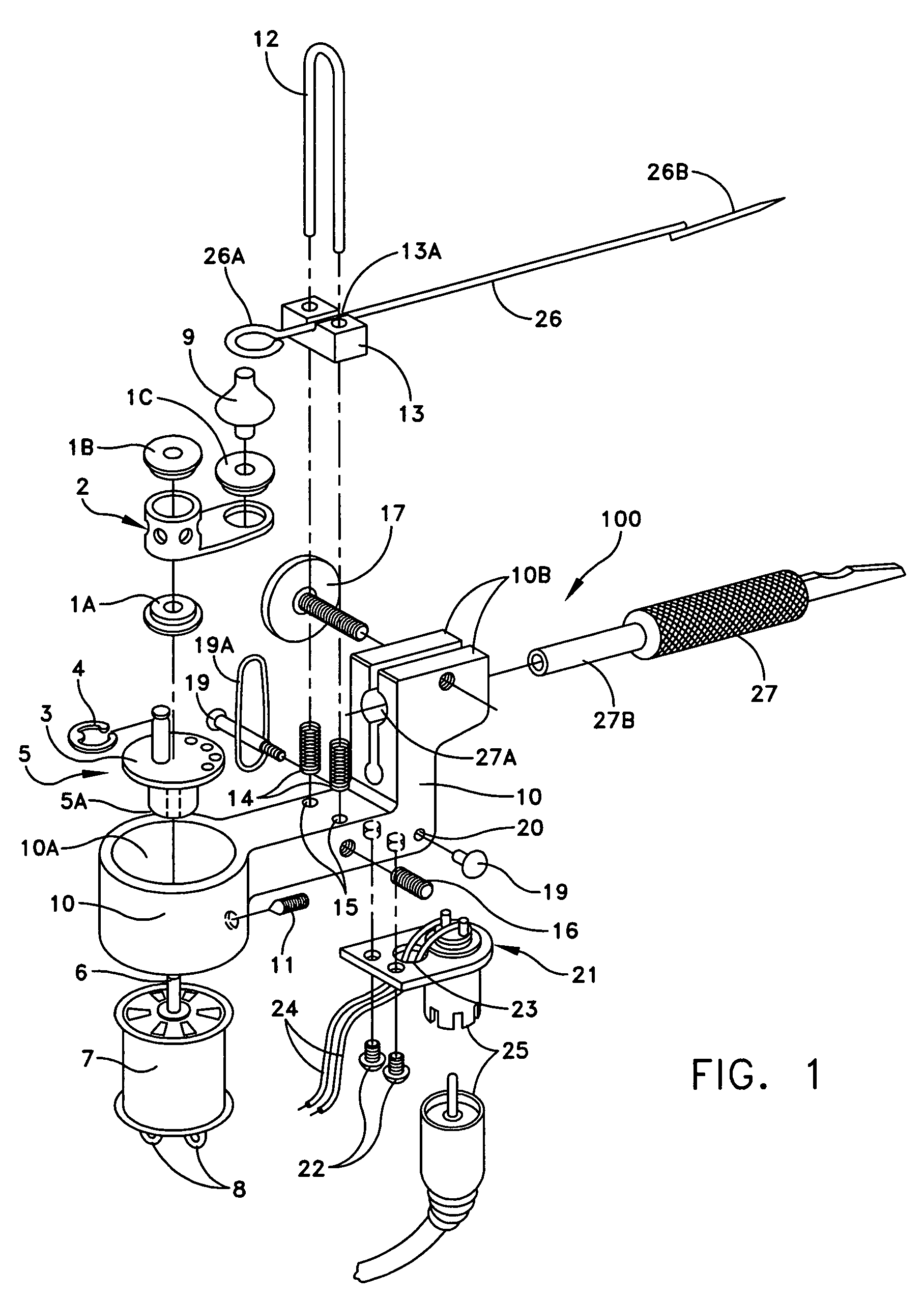
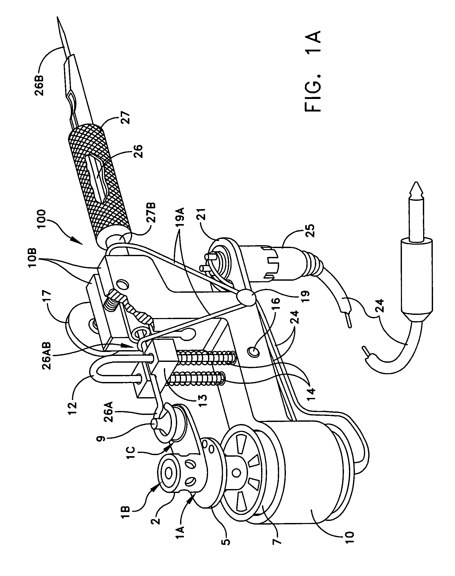
[0012]FIG. 1 illustrates an exploded view of the Universal Rotary Device 100 in its disassembled state. FIG. 1A illustrates a Universal Rotary Device 100 in its assembled state. Referring to FIGS. 1 and 1A, power to rotary device 100 is supplied through RCA jack 25 via a 12 volt power supply and interrupter switch (not shown). Bracket 21 houses female end of RCA Jack 25 and is secured to frame 10 by screws 22. Low voltage wires 24 connect motor 7 to RCA jack 25 at motor solder tabs 8. Frame 10 includes opening 10A and lock screws 11 which secure motor 7 in frame 10 and allow for rapid and easy replacement of motor 7 if necessary. In the preferred embodiment, the opening is circular, however, it is understood that any opening necessary to accomodate any dimension motor could be utilized. Motor 7 allows for variable rotational motion of motor shaft 6 over a speed range of approximately 3000 to 8500 RPMs. Motor shaft 6 engages a drive mechanism which comprises a counter balance flywhee...


PUM


Abstract

A marking device with a reciprocating needle is disclosed. The needle is attached to a drive mechanism that is linearly reciprocated via a drive motor. The needle is contained within a removable grip tube for adjustability of the exposed length of the needle end, the needle further including a stabilization mechanism limiting the movements of the needle to linear reciprocating motion. The device includes an open design for easy removal and replacement of device components and allows for utilization of varying dimensioned components such as tubes, needles, and motors available from a variety of manufacturers.

Description

CROSS REFERENCE TO RELATED APPLICATIONS[0001]This application claims the benefit of U.S. Provisional Application No. 60 / 608,477 filed 10 Sep. 2004.FIELD OF THE INVENTION[0002]This invention relates to a reciprocating shaft device for marking of articles and for identification of the skin of animals or humans, and more specifically to a tattoo device including such a reciprocating shaft device.BACKGROUND OF THE INVENTION[0003]Devices in the field of the present invention are used to place ink below the surface of an object or article. A pin or needle punctures the surface and places the ink below the surface. When the surface of the skin is a living being, the ink is placed at such a level in the skin where it remains permanently. Because the ink is permanent, it is very important that the ink be applied very precisely. Correspondingly, it is very important that the position of the needle when it punctures the surface can be precisely controlled. The needle must be moved back and for...

Claims


Application Information

Patent Timeline
IPC IPC(8): B43K5/00
CPCA61M37/0076B43L13/24
Inventor DAIGLE, RONALD
Owner DAIGLE RONALD
Why Eureka
Try Eureka