
Projection type video display

Inactive Publication Date: 2007-04-24
SANYO ELECTRIC CO LTD
View PDF24 Cites 25 Cited by
  • Summary
  • Abstract
  • Description
  • Claims
  • Application Information

AI Technical Summary

Benefits of technology

[0005]However, it is desired to further improve contrast and reduce power consumption. Further, in a liquid crystal projector, black floating (incomplete reproduction of black color) which is its weakness must be restrained.
[0006]In view of the foregoing circumstances, an object of the present invention is to provide a projection type video display capable of achieving improvement in contrast, reduction in power consumption, and restraint of black floating in a case where a liquid crystal projector is used as a projection type video display.
[0008]In the above-mentioned configuration, a video to be projected is brightened by increasing the amount of emitted light when a bright video is projected, while being darkened by reducing the amount of emitted light when a dark video is projected, thereby improving contrast. Further, power consumption is also reduced by reducing the amount of emitted light, thereby improving an energy saving effect. When a liquid crystal light valve is used as a light valve, black floating is restrained.
[0011]In a projection type video display that optically modulates light emitted from a light source by a light valve and projects a video, a projection type video display according to the present invention is characterized by comprising a shading adjustment unit for adjusting shading of illuminating light from a light source; means for generating a signal representing the APL of a video on the basis of a video signal; and control means for carrying out such control as to reduce an amount of shading by the shading adjustment unit when the signal represents a high level, while increasing the amount of shading by the shading adjustment unit when it represents a low level.

Problems solved by technology

Further, in a liquid crystal projector, black floating (incomplete reproduction of black color) which is its weakness must be restrained.

Method used


Image

  • Projection type video display
  • Projection type video display
  • Projection type video display

Examples


Embodiment Construction

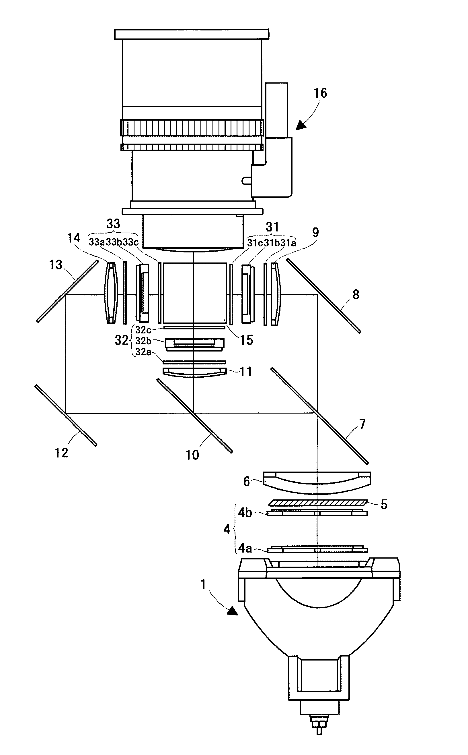
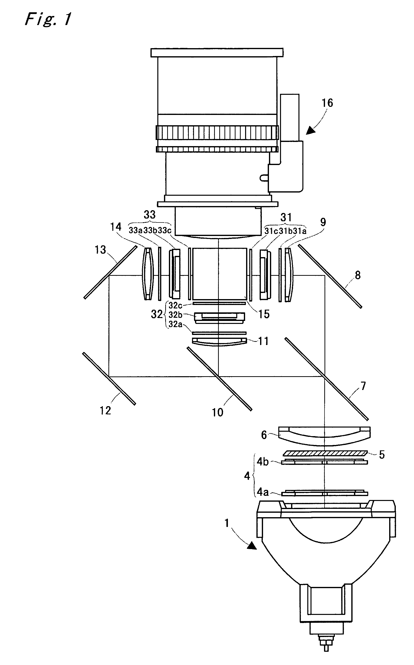
[0022]A liquid crystal projector according to an embodiment of the present invention will be described on the basis of FIGS. 1 to 5.

[0023]FIG. 1 is a diagram showing a three-panel liquid crystal projector according to the present embodiment. A light emitting portion in a light source 1 is composed of a ultra-high pressure mercury lamp, a metal halide lamp, a xenon lamp, or the like, and its irradiated light is emitted after being changed into parallel lights by a parabolic reflector, and is introduced into an integrator lens 4.

[0024]The integrator lens 4 is composed of a pair of groups of lenses (fly's eye lenses) 4a and 4b, and each of lenses composing the fly's eye lens introduces light emitted from the light source 1 into the whole surface of a liquid crystal light valve, described later, to average partial non-uniformity in luminance which exists in the light source 1 and reduce the difference between light amounts at the center and the periphery of the screen. The light which h...


PUM


Abstract

A video signal processing circuit inputs a video signal to perform processing such as frequency conversion as well as processing for generating data representing the APL (Average Picture Level) of a frame video for each frame period. A microcomputer functions as a dimmer arithmetic block to perform processing for generating dimmer data upon receipt of APL data, and functions as a lamp driver control block to perform processing for sending out a dimmer command to a lamp driver. The lamp driver receives the dimmer command, to control an amount of light emitted from a light source (a lamp).

Description

BACKGROUND OF THE INVENTION[0001]1. Field of the Invention[0002]The present invention relates to a projection type video display such as a liquid crystal projector.[0003]2. Description of the Background Art[0004]Conventionally, a liquid crystal display so adapted that display luminance and contrast are made constant even when the APL (Average Picture Level) of a video is changed (see JP-A-08-201812), or a projection type video display for reducing lamp driving power when the APL of a video is high, while increasing lamp driving power when it is low, to improve contrast (see JP-A-03-179886) has been proposed.SUMMARY OF THE INVENTION[0005]However, it is desired to further improve contrast and reduce power consumption. Further, in a liquid crystal projector, black floating (incomplete reproduction of black color) which is its weakness must be restrained.[0006]In view of the foregoing circumstances, an object of the present invention is to provide a projection type video display capable...

Claims


Application Information

Patent Timeline
IPC IPC(8): G03B21/14F21V17/02G02F1/1335G03B21/20H04N9/31G03B21/00G02B26/00G02B27/18G02F1/13H04N5/74
CPCG03B21/14G03B21/2053
Inventor TOTANI, TAKAHIROTERADA, KATSUMIKOBA, HIROKIOKETANI, KAZUNOBU
Owner SANYO ELECTRIC CO LTD
Learn More