Birth monitoring system

a technology of position monitoring and monitoring system, which is applied in the field of intrabody position monitoring system, can solve the problems of a large amount of dilatation of the cervix, a complicated and traumatic process of human childbirth, and surprising little known

Inactive Publication Date: 2007-04-24
BARNEV
View PDF60 Cites 101 Cited by
  • Summary
  • Abstract
  • Description
  • Claims
  • Application Information

AI Technical Summary

Problems solved by technology

The birth of a human child is a complicated and traumatic process, of whose mechanical and geometrical aspects, surprisingly little is known.
First, however, the head must exit the uterus through the cervix, which requires the cervix to dilate a large amount.
However, this measurement method is not only unsanitary, it is also intrusive and inaccurate.
These variations cannot be measured continuously in a reliable manner manually, reducing the amount of information available, for example, the effect of each contraction.
One potential problem with this approach is that wires are required to connect to the ultrasonic sensors inside the body.
Providing ultrasonic transmitters inside the body may not be a viable solution, due to their size.
Using ultrasonic transmitter / receivers or reflectors may also be difficult, since they require transmission of ultrasound through tissue which may suffer from noise degradation and other effects (e.g., due to the many interfaces between different materials, significant accuracy and signal to noise problems may be experienced).

Method used


Image

  • Birth monitoring system
  • Birth monitoring system
  • Birth monitoring system

Examples


Embodiment Construction

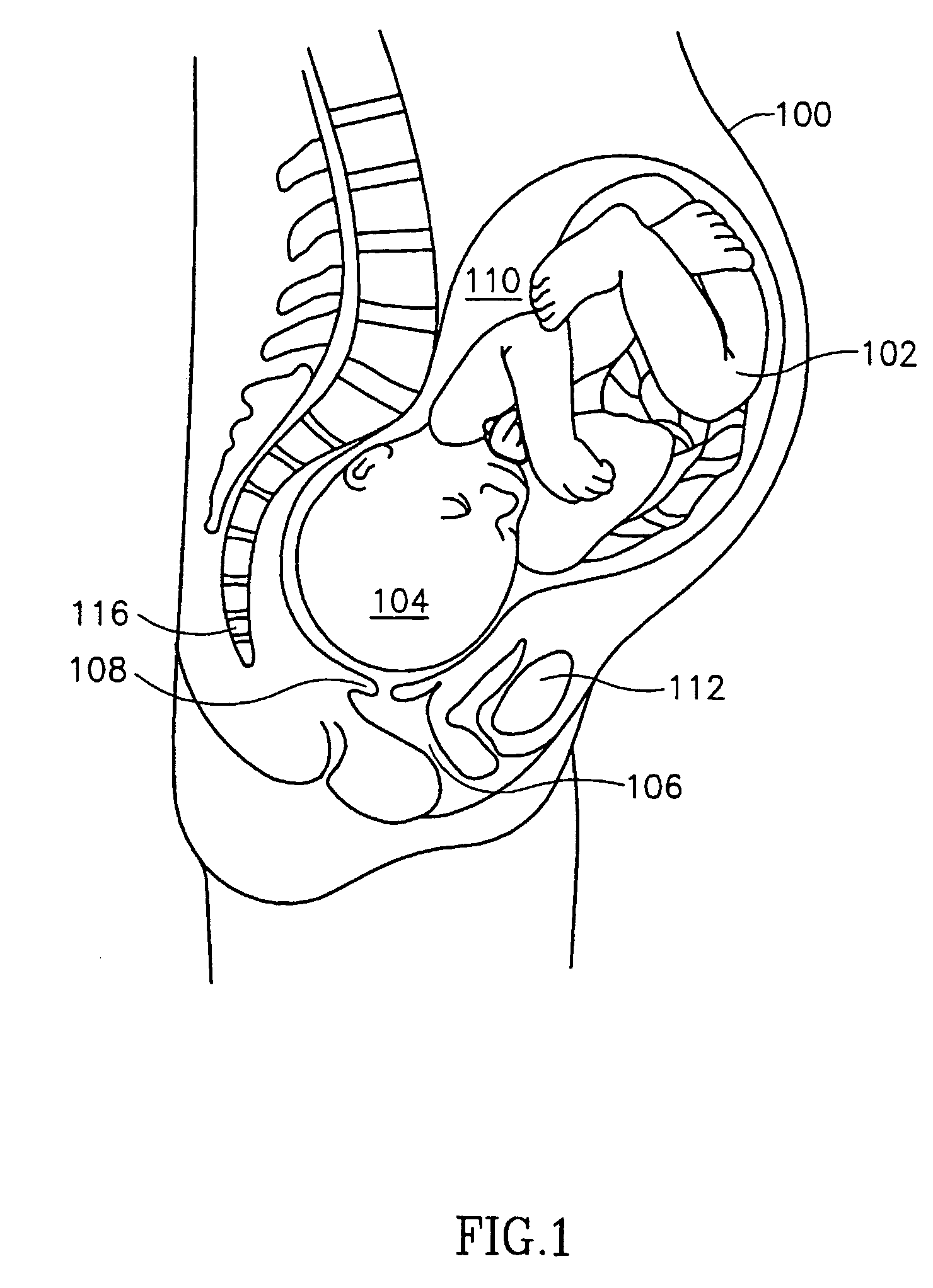
[0075]FIG. 1 shows is a side schematic view of a birth canal and uterus containing a fetus during normal vertex delivery, on which the methods and / or apparatus of some embodiments of the present invention are applied.

[0076]A supine mother 100 has a uterus 110 with a fetus 102 inside. In this figure, fetus 102 has its head 104 pointed forward, towards an opening 114 in a cervix 108. Once the cervix is dilated, fetus 102 will pass through a birth canal 106 and be born. Spine 116 and pelvic bone112 constrain the path, forcing the fetus to bend and twist during the birthing (the side pelvic bone are not shown). This example is used for reason of convenience, however, various embodiments of the present invention may be usefully used also when the fetus has a different presentation than the one shown.

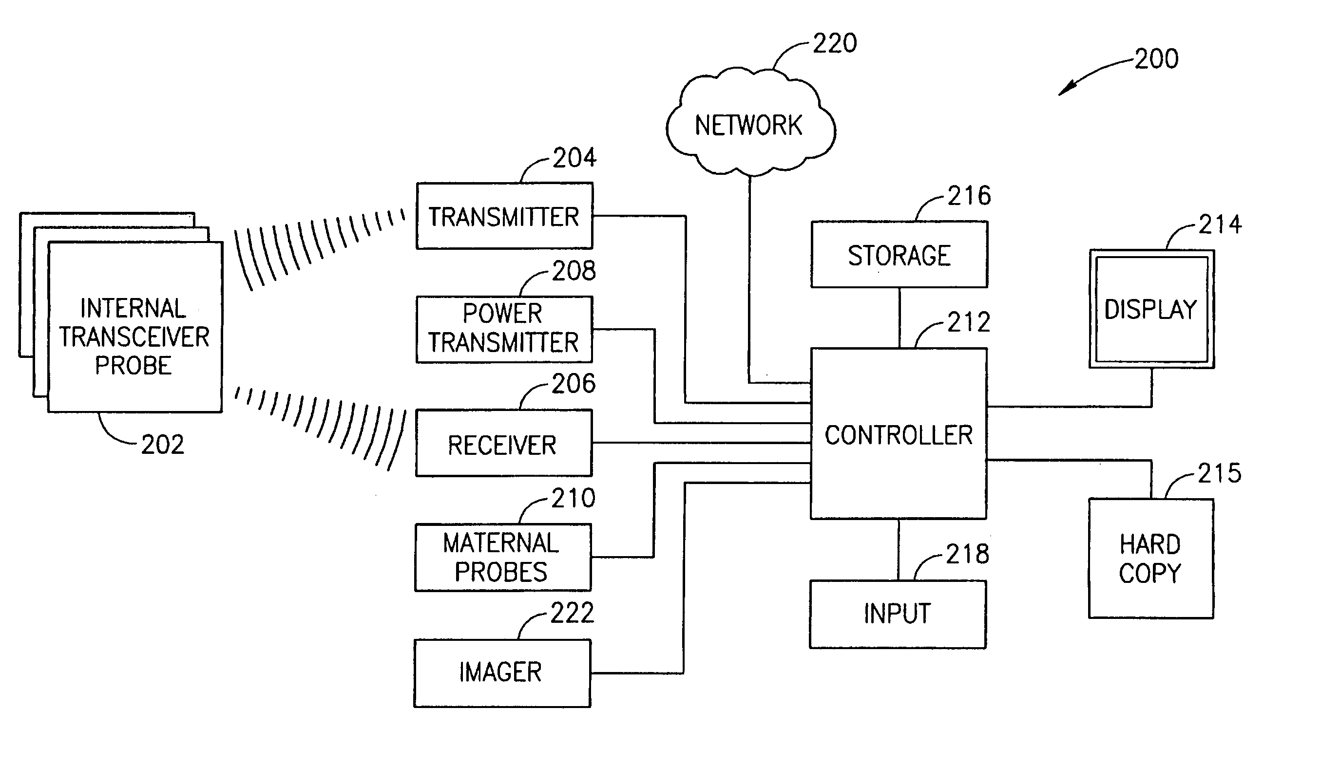
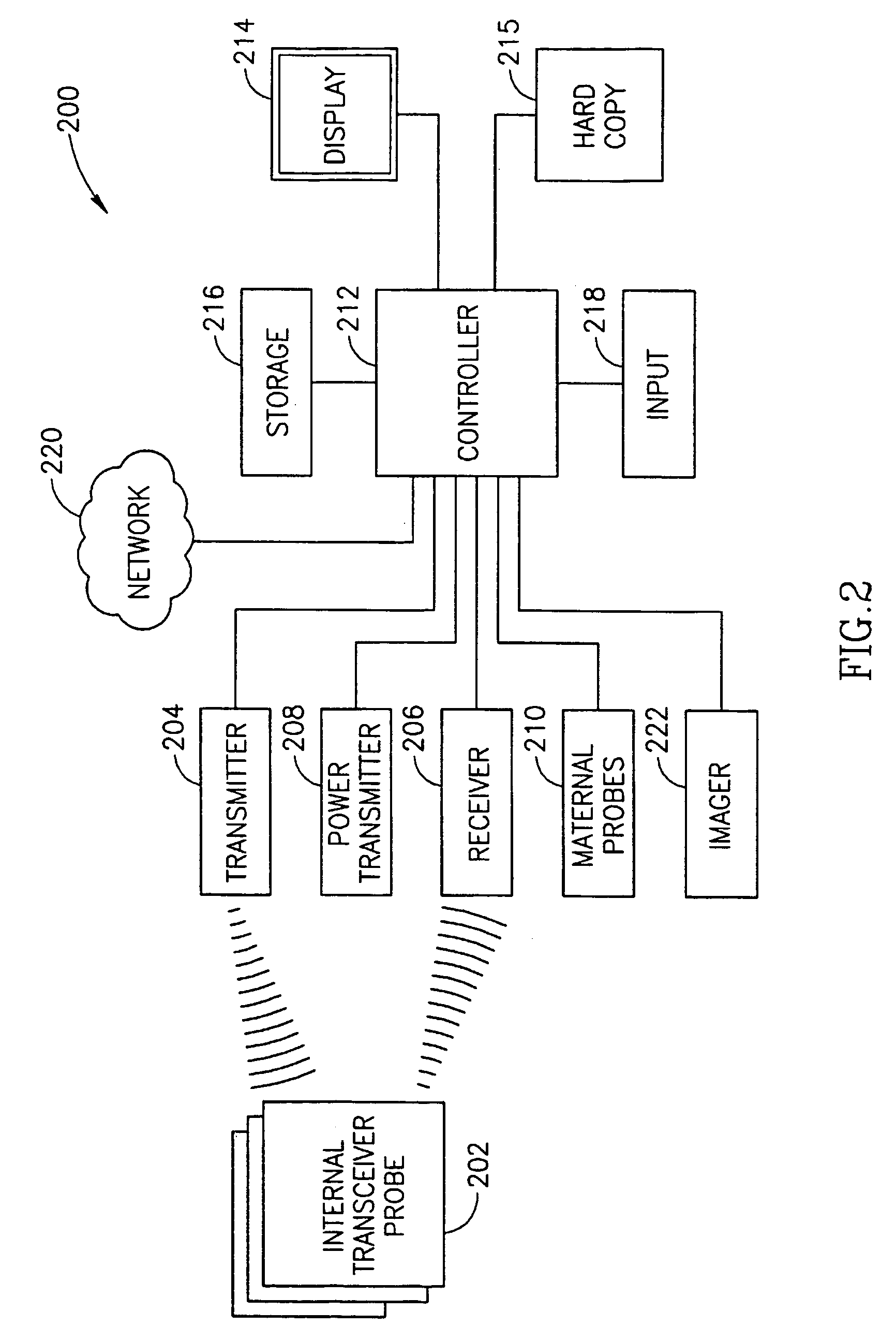
[0077]FIG. 2 is a schematic block diagram of a birth monitoring system 200 in accordance with an exemplary embodiment of the invention. System 200 comprises at least one internal transducer p...


PUM


Abstract

A medical transponder, including an ultrasonic sensor that detects impinging ultrasonic waves and generates electrical signals in response thereto; an electrical connection which receives said signals; and an electromagnetic RF transmitter coupled to said electrical connection and which generates an RF signal in response to said detected waves.

Description

RELATED APPLICATIONS[0001]This application is a U.S. National filing of PCT / IL / 02 / 00440 filed Jun. 5, 2002. This application also claims the benefit under 119(e) of the following provisional applications: 60 / 295,569 filed 5 Jun. 2001, 60 / 295,573, filed 5 Jun. 2001, 60 / 309,783, filed 6 Aug. 2001 and 60 / 338,671, filed Dec. 11, 2001. This application is also related to PCT / IL / 02 / 00441 filed Jun. 5, 2002, the disclosure of all of these applications is incorporated herein by reference.FIELD OF THE INVENTION[0002]The present invention relates to intrabody position monitoring systems.BACKGROUND OF THE INVENTION[0003]The birth of a human child is a complicated and traumatic process, of whose mechanical and geometrical aspects, surprisingly little is known. In a normal birth, the cervix dilates and a fetus is pushed out from a uterus and along a birth canal (e.g., the vagina), which lies between the pubic bones. This is described in greater detail, for example, in Williams Obstetrics Cunning...

Claims


Application Information

Patent Timeline
Patent Type & Authority Patents(United States)
IPC IPC(8): A61B8/00A61B5/103A61B5/00A61B5/024A61B5/06A61B5/07A61B5/107A61B5/11A61B5/288A61B8/08A61B8/12A61B17/42A61D1/08G01S13/74G01S15/74
CPCA61B5/0031A61B5/076A61B5/1127A61B5/6882A61B8/0866A61B8/12A61B8/4472A61B8/565A61B5/0448A61B5/06A61B5/1076A61B8/0833A61B8/4281A61B2503/02A61B2562/226A61B8/56A61B5/02411A61B5/288
Inventor SHARF, YEHUDA
Owner BARNEV
Why Eureka
Try Eureka