Transmitting type secondary electron surface and electron tube
a technology of electron tube and secondary electron surface, which is applied in the direction of electron multiplier details, image-conversion/image-amplification tubes, and tubes with screens, etc., can solve the problems that the emission efficiency of secondary electrons of secondary electron emitters has not been practical, and achieves the reduction of secondary electron emission efficiency and high efficiency. , the effect of improving the emission efficiency of secondary electrons according to the primary electron
- Summary
- Abstract
- Description
- Claims
- Application Information
AI Technical Summary
Benefits of technology
Problems solved by technology
Method used
Image
Examples
first embodiment
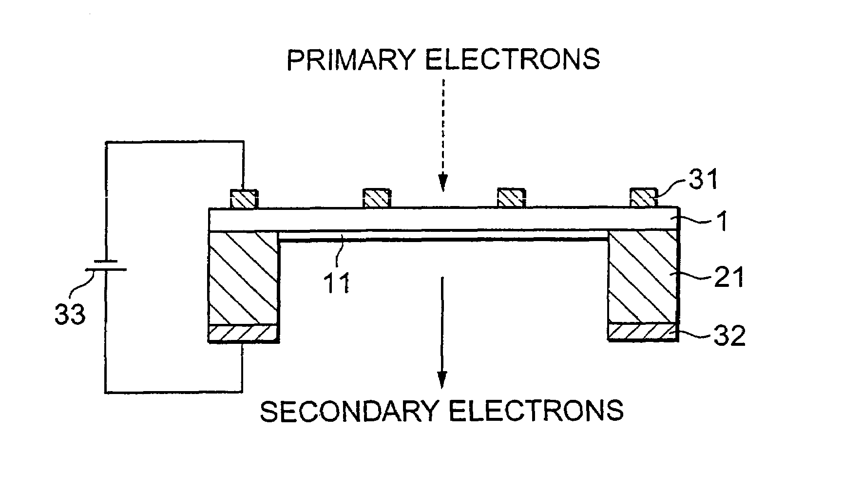
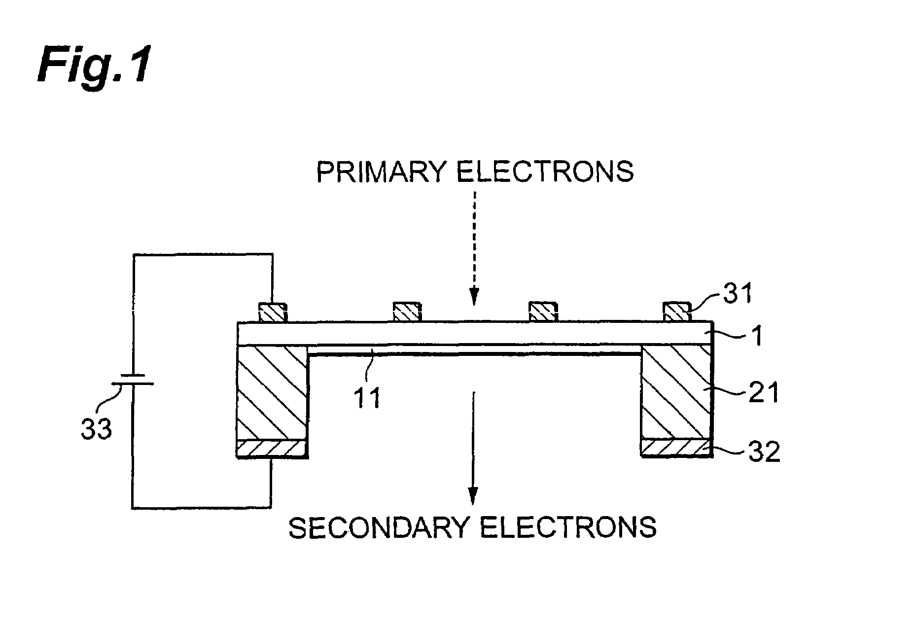
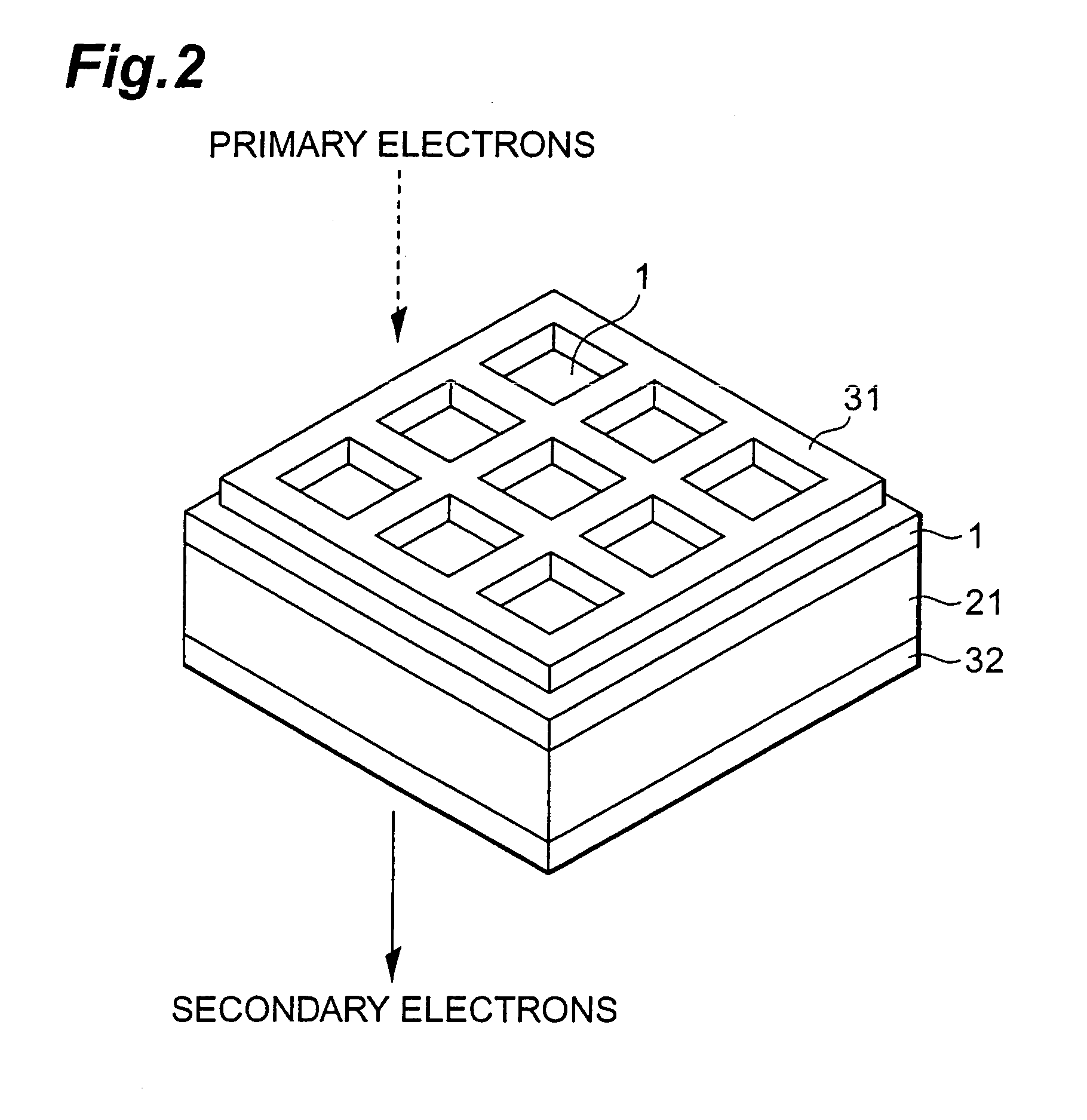
[0027]FIG. 1 is a side cross-sectional view illustrating the construction of a transmission secondary electron emitter according to the present invention. FIG. 2 is a perspective view of the transmission secondary electron emitter shown in FIG. 1.
[0028]A transmission secondary electron emitter illustrated in FIG. 1 comprises a secondary electron emitting layer 1, a supporting frame 21, a first electrode 31 and a second electrode 32. In the transmission secondary electron emitter, secondary electrons are generated in the secondary electron emitting layer 1 by an incidence of primary electrons, and secondary electrons are emitted outside. The transmission secondary electron emitter has a transmission type construction. One surface (an upper surface in FIG. 1) of the secondary electron emitting layer 1 is the surface of the incidence for making the primary electrons incident thereon, and the other surface (a lower surface in FIG. 1) of the side opposite thereto is the surface of the em...
second embodiment
[0053]FIG. 4 is a side cross-sectional view illustrating the construction of the transmission secondary electron emitter according to the
[0054]The transmission secondary electron emitter shown in FIG. 4 comprises the secondary electron emitting layer 1, the active layer 11, the supporting frame 21, a first electrode film 31a, an auxiliary electrode 34 and the second electrode 32. Of these, the constructions of the secondary electron emitting layer 1, the active layer 11, the supporting frame 21 and the second electrode 32 are identical to those of the transmission secondary electron emitter shown in FIG. 1.
[0055]The first electrode film 31a is formed in the film state on the surface of the incidence of the secondary electron emitting layer 1. The first electrode film 31a is very thinly formed (the thickness of about 30 to 150 Å) such that the secondary electrons generated in the secondary electron emitting layer 1 are not absorbed by the first electrode film 31a. The auxiliary elect...
third embodiment
[0060]FIG. 5 is a side cross-sectional view illustrating the construction of the transmission secondary electron emitter according to the
[0061]The transmission secondary electron emitter shown in FIG. 5 comprises the secondary electron emitting layer 1, the active layer 11, a supporting frame 22, a first electrode 35 and a second electrode 36. Of these, the constructions of the secondary electron emitting layer 1 and the active layer 11 are identical to those of the transmission secondary electron emitter shown in FIG. 1.
[0062]The supporting frame 22 is a supporting means for reinforcing the mechanical strength of the secondary electron emitting layer 1 formed thinly. The supporting frame 22 is arranged on the outer edge part of the surface of the incidence of the secondary electron emitting layer 1.
[0063]The first electrode 35 formed on the surface of the incidence of the secondary electron emitting layer 1 is an electrode of an incident surface side. In this embodiment, the first ...
PUM
 Abstract
Description
Claims
Application Information
 - R&D
- Intellectual Property
- Life Sciences
- Materials
- Tech Scout
- Unparalleled Data Quality
- Higher Quality Content
- 60% Fewer Hallucinations
Browse by: Latest US Patents, China's latest patents, Technical Efficacy Thesaurus, Application Domain, Technology Topic, Popular Technical Reports.
© 2025 PatSnap. All rights reserved.Legal|Privacy policy|Modern Slavery Act Transparency Statement|Sitemap|About US| Contact US: help@patsnap.com


