Leak-tight system for boxes containing electrical and electronic components

a technology of leak-tight boxes and electronic components, which is applied in the direction of electrical apparatus casings/cabinets/drawers, electrical apparatus connection, semiconductor/solid-state device details, etc., can solve the problems of reducing the dimensions of such electronic modules, affecting the efficiency of the system, so as to prevent moisture from reducing the dielectric strength

Inactive Publication Date: 2007-04-24
LEAR CORP
View PDF17 Cites 25 Cited by
  • Summary
  • Abstract
  • Description
  • Claims
  • Application Information

AI Technical Summary

Benefits of technology

[0002]The object of the invention is to prevent moisture from decreasing the dielectric strength between the tracks and components of the printed circuit board or boards bearing them, to in turn prevent effects of electromigration which usually generate unwanted signals and other failures.

Problems solved by technology

On the other hand, there is also a generalized tendency to reduce the dimensions of such electronic modules, and accordingly of the box containing them, which in many cases implies the necessity of bringing the electroconductive tracks of the printed circuit board or boards excessively close to one another, which favors electromigration due to the effect of moisture.
Furthermore, many of such electronic modules generate a substantial amount of heat, which must be dissipated, occasionally with the cooperation of radiators duly associated to certain components.
The housing of these elements inside the box makes the heat dissipation very difficult considering that to prevent the problem of the moisture, it is necessary for the closure of the box to be leak-tight, as previously stated, such that the temperature inside them can reach levels implying a risk of deterioration for said components.
The problem of electromigration is solved by means of applying an insulating varnish to the printed circuit board or boards, but the protection index against it is insufficient in many cases and, furthermore, does not solve the problem of heat dissipation.

Method used


Image

  • Leak-tight system for boxes containing electrical and electronic components
  • Leak-tight system for boxes containing electrical and electronic components
  • Leak-tight system for boxes containing electrical and electronic components

Examples


Embodiment Construction

[0009]The system proposed by the invention solves in a fully satisfactory manner the drawbacks set forth above in the different aspects discussed.

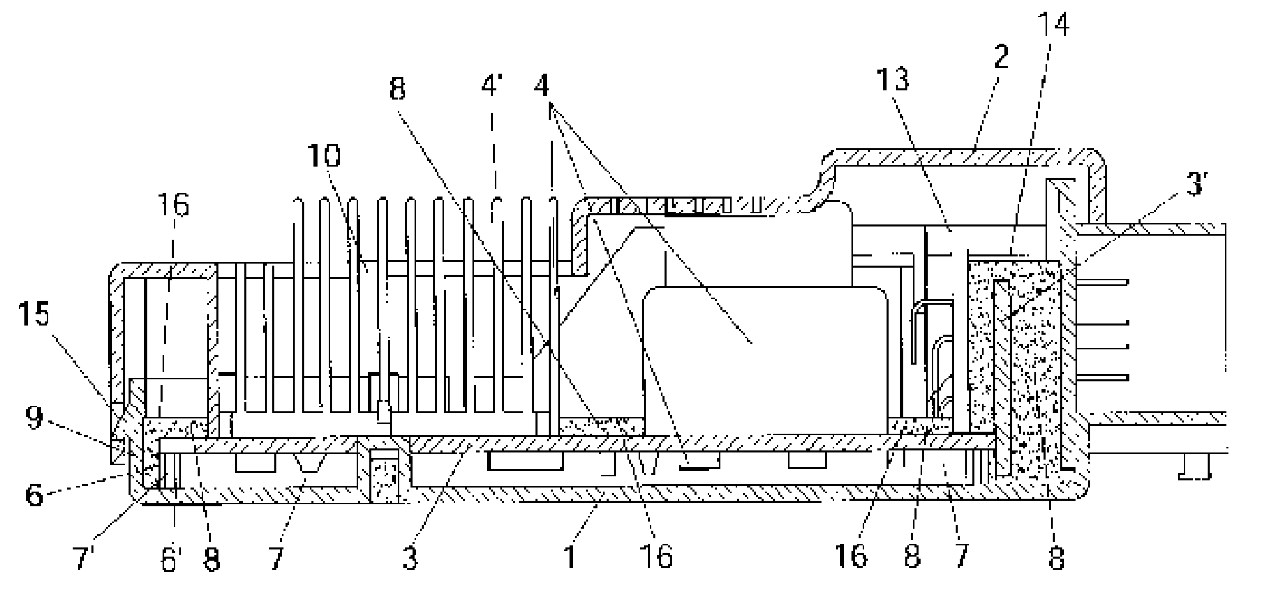
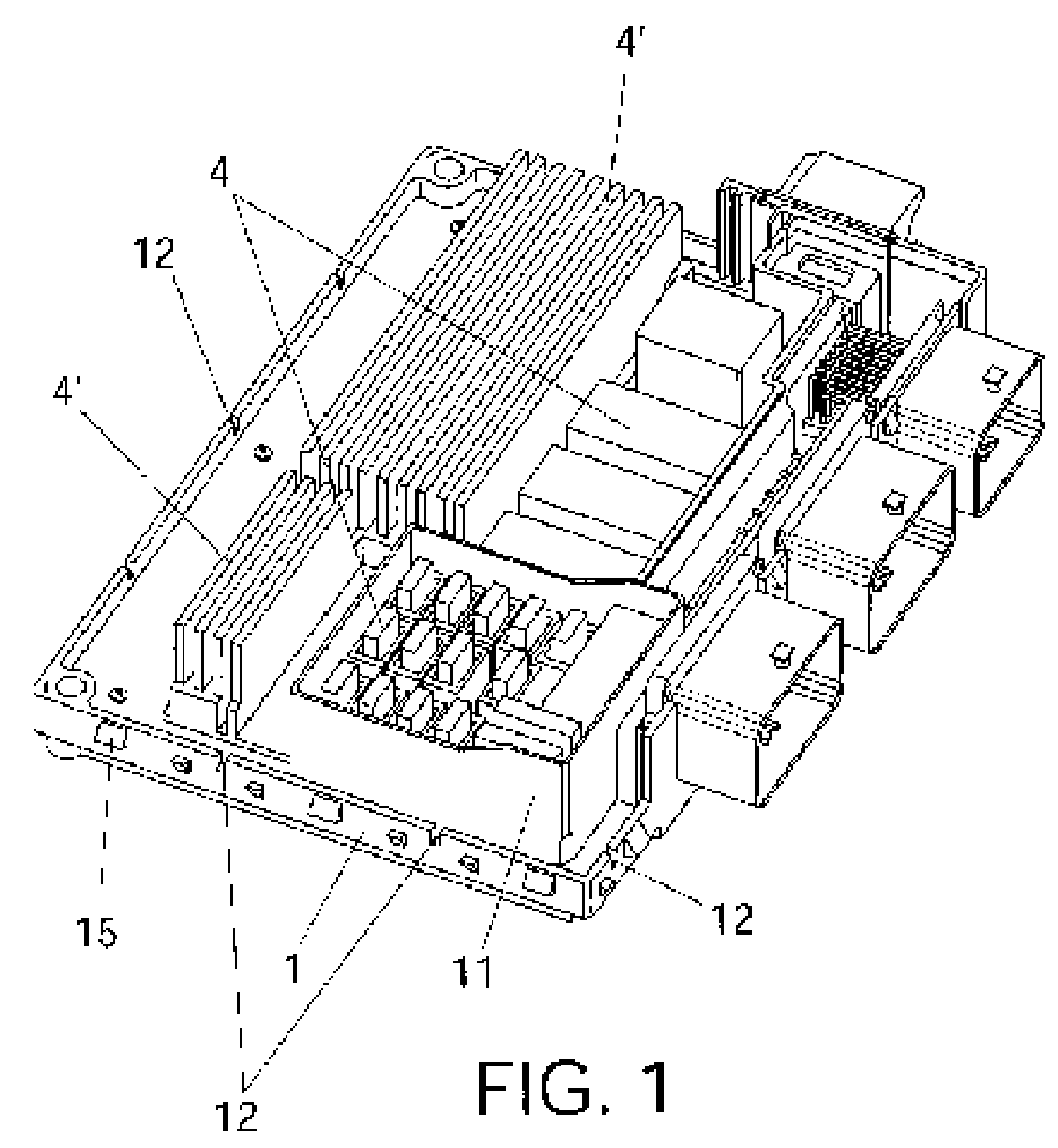
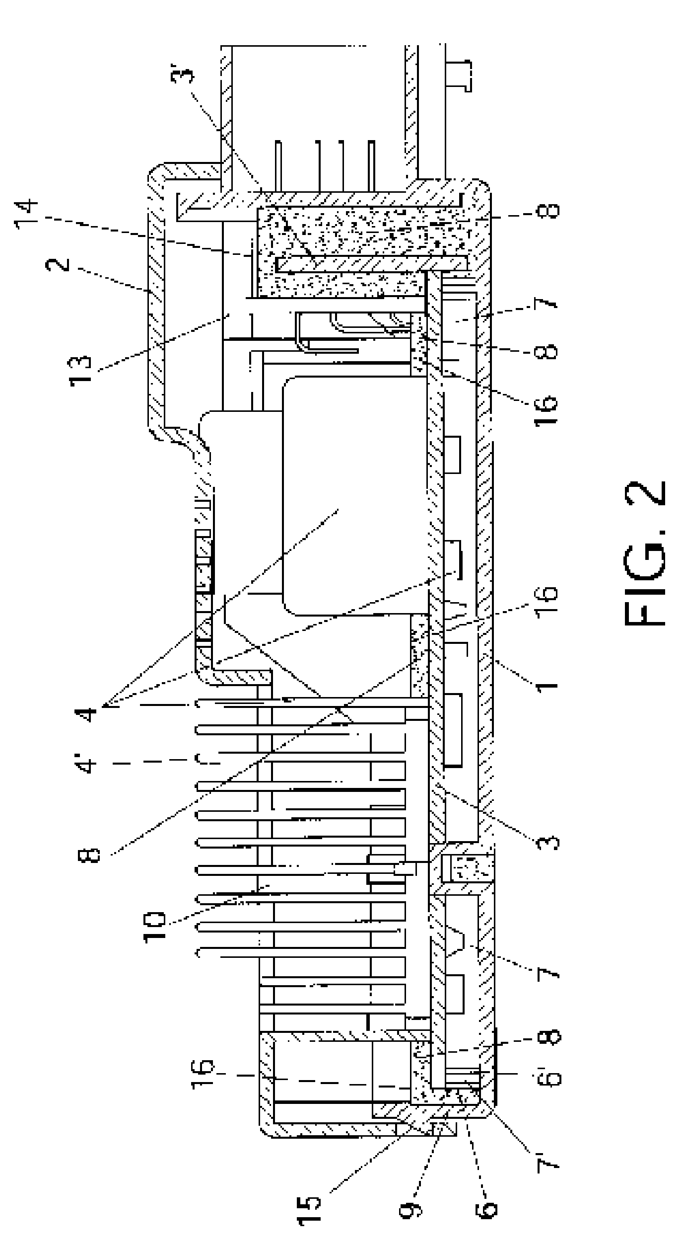
[0010]To that end, more specifically and according to one of the features of the invention, rather than achieving the leak-tightness by means of an also leak-tight coupling between the body and the cover of the box, said leak-tightness is obtained by providing the printed circuit board with a perimetral support flap distancing it from the bottom of the box, such that defined between the printed circuit board, flap and bottom of the box is a chamber in which the components associated to the printed circuit board on its lower side are housed.

[0011]This chamber is thereby definitively made leak-tight, and said components are consequently protected against the effects of moisture, by means of pouring on the printed circuit board a suitable amount of resin in liquid state, which solidifies immediately afterwards, which on one hand acts as a sea...


PUM


Abstract

The system consists of fixing the printed circuit board (3) to the bottom (1) of the body of the box with the cooperation of a perimetral and spacing flap (6) which creates a chamber (7) under the board (3), in which the components (4) associated to the lower side of said board are housed, subsequently filling the outer perimetral space of said flap (6) with a resin mass (8), which is applied in liquid state and solidifies immediately afterwards, such that said resin (8) perfectly seals the chamber (7), while at the same time provides a thick protective layer on the upper side of the printed circuit board (3), also protecting the latter, which allows for the cover (2) of the box to have openings for ventilation of certain components (4′) which generate a remarkable amount of heat.

Description

OBJECT OF THE INVENTION[0001]The present invention refers to a system which has been specially designed to achieve a perfect protection of the electrical and electronic components located inside a distribution box or the like against the effects of ambient moisture.[0002]The object of the invention is to prevent moisture from decreasing the dielectric strength between the tracks and components of the printed circuit board or boards bearing them, to in turn prevent effects of electromigration which usually generate unwanted signals and other failures.[0003]The invention is of particular application in the automotive field, particularly in that of electrical systems for automobiles.BACKGROUND OF THE INVENTION[0004]There is currently a widespread use of electronic modules, power distribution boxes and / or electronics and power boxes, having a high number of electrical and electronic components, assembled on one or more printed circuit boards, which modules, due to their own nature and e...

Claims


Application Information

Patent Timeline
Patent Type & Authority Patents(United States)
IPC IPC(8): H05K7/02H01L23/28H05K7/14
CPCH05K5/064H05K7/1417
Inventor YARZA, JORGE GIMENEZ
Owner LEAR CORP
Why Eureka
Try Eureka