
Detachable process unit including a charge elimination mechanism

a technology of charge elimination mechanism and process unit, which is applied in the field of image forming machines, can solve the problem of very weak noise due to discharg

Active Publication Date: 2007-04-24
KYOCERA DOCUMENT SOLUTIONS INC
View PDF13 Cites 5 Cited by
  • Summary
  • Abstract
  • Description
  • Claims
  • Application Information

AI Technical Summary

Benefits of technology

The present invention proposes an image forming machine with a detachable image carrier device for forming toner images using an electrophotographic method. The machine has guide grooves in its base frames for positioning the image carrier device, and a contact member that comes into contact with the conductive shaft of the image carrier device when the unit is positioned in place. A charge eliminating member is also provided to eliminate the electric charge accumulated on the image carrier device, preventing noise interference with the initializing program in the controller. The charge eliminating member can be a conductive brush or a metal plate that comes into contact with the conductive shaft when the unit is detached or attached. This invention reduces the amount of remaining charge and prevents malfunctions and noise interference during image formation.

Problems solved by technology

Therefore, even if discharge occurs by chance between the conductive shaft of the image carrier device and the contact member when detaching and then attaching the unit to be positioned in place (in the position where the conductive shaft of the image carrier device is positioned in the guide groove when image formation is carried out), the noise due to the discharge is very weak.

Method used


Image

  • Detachable process unit including a charge elimination mechanism
  • Detachable process unit including a charge elimination mechanism
  • Detachable process unit including a charge elimination mechanism

Examples


first embodiment

[0034]In FIG. 3FIG. 6, reference numeral 40 is the charge eliminating brush as a charge eliminating member of the first embodiment for allowing the electric charge accumulated on the image carrier device 8 in the image forming machine of the present invention to be corona-discharged, 41 is a brush holder, 42 are brush ears made of conductive thin strings or threads shaped, for example, by extruding the mixture of resin and copper powder. As to the conductive thin string or thread, the one made of polycarbonate thin string or thread coated with copper sulfide, the volume specific resistance of the thin string or thread being 1˜0.01 Ω·cm, which is available as the product name of Thunderon produced by TSUCHIYA TSCO COMPANY, Ltd., can be used, and any other products having the same effect may be used. Reference numeral 43 is a gear attached to the shaft of the motor 12, 44 is a gear for driving the process unit. Referring to FIG. 7, reference numeral 60 is an example of a process unit ...

second embodiment

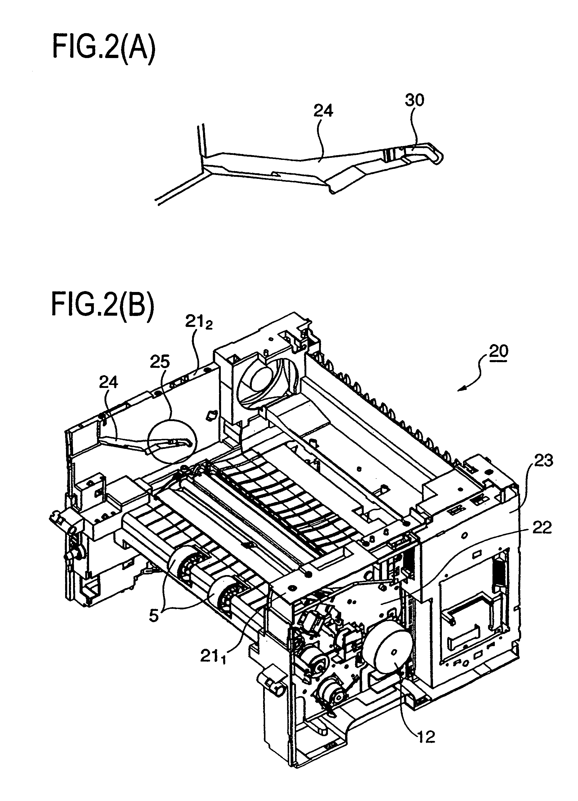
[0044]The charge eliminating member (ground plate) 70 of leaf spring shape of the second embodiment shown in FIG. 8 has a crest part 72, a hole 73 for attaching the member to the drive plate 22 by means of a tightening vis, etc., an end part 71 for inserting in a slit or hole 75 provided in the drive plate 22, and a claw part 74 for inserting in a slit or hole 76 provided in the drive plate 22. The member 70 is attached to the drive plate 22 as shown in FIG. 8(B) by inserting the claw part 74 in the slit or hole 76, inserting the end part 71 in the slit or hole 75, and tightening the vis. When the drive plate 22 is attached to the base frame 211, the ground plate 70 protrudes in the guide groove 26 as shown in FIG. 9. When the process unit 60 is attached to or detached from the machine body 20, the conductive shaft 61 of the process unit 60 can smoothly passes over the crest part 72 of the ground plate 70 because the crest part 72 is pushed by the end face of the conductive shaft 61...

fifth embodiment

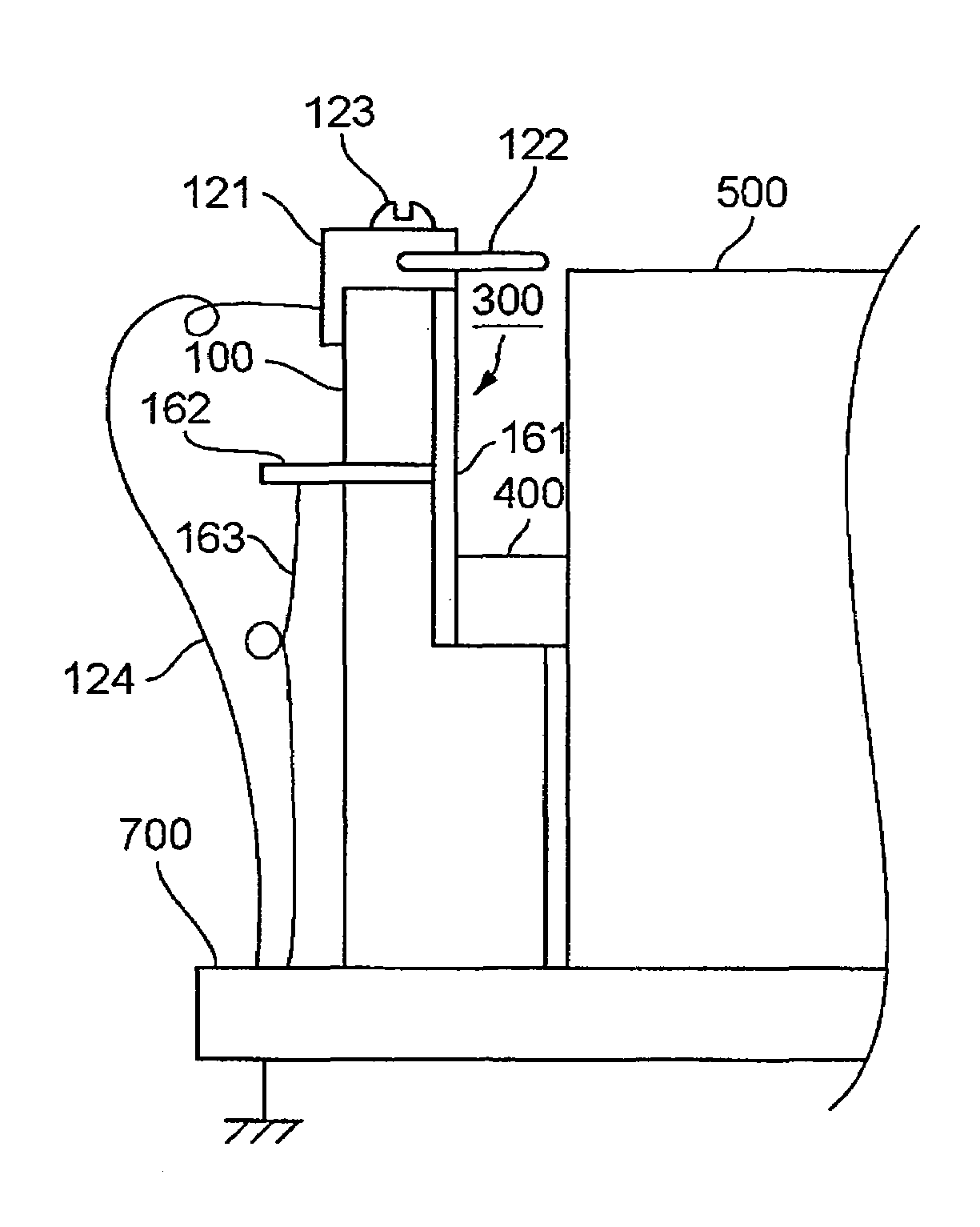
[0060]Although the discharge of the process unit by the three kinds of discharge members (discharge brush 122, bent metal spring plate 125 and metal mesh 126) were explained, there are several modifications for the The discharge member may be provided on at least one of the side plates. Further, the conductive axis or electrical conductive shaft may be a rotating or fixed axis of the photoreceptor drum.

[0061]The rotating axis is fixed and unified with the photoreceptor drum (conductive cylinder substrate of the photoreceptor) by using a conductive flange between them. The end surface of the rotating axis contacts the conductive member 161 in the guide groove 300, thereby grounding the inner surface of the conductive cylinder substrate. Further, the rotating axis is extracted from the inside of the process unit 500 through a sliding bearing made of, e.g., polyacetal resin.

[0062]On the other hand, the fixed axis is sliding through a metallic spring plate on a rotating conductive flan...


PUM


Abstract

When a sheet jams in an image forming machine with a detachable unit having at least an image carrier device, it is necessary to detach the unit to remove the sheet when the image carrier device is charged with electric charge. When the unit is detached and re-attached, spark discharging may occur inducing noise upon a contact of an electrically conductive shaft of the image carrier device to a ground conductor. The present invention prevents the occurrence of such a problem. Guide grooves are provided to a base frames of the image forming machine to guide both end parts of the electrically conductive shaft of the image carrier device to position the unit in place, and a charge eliminating member is provided upstream from the position for allowing the electric charge accumulated on the image carrier device to be corona-discharged by way of the electrically conductive shaft to remove the accumulated charge.

Description

CROSS-REFERENCE TO RELATED APPLICATIONS[0001]The present application is a Continuation-in-Part Application of, and claims priority from, U.S. patent application Ser. No. 10 / 832,453 entitled “Image Forming Apparatus” filed on Apr. 27, 2004 now U.S. Pat. No. 7,035,566, the contents of which are incorporated herein by reference.BACKGROUND OF THE INVENTION[0002]The present invention is related to an image forming machine such as a copying machine, printer, facsimile machine, and combined machine of them using an electrophotographic process, specifically to an image forming machine composed such that a unit integrating at least an electric charging device and an image carrier device is detachably mounted or only an image carrier device is detachably mounted and a mechanism is provided for removing the electric charge accumulated in the process of detaching or attaching the unit from or to the image forming machine body.[0003]In the field of image forming machines such as copying machines...

Claims


Application Information

Patent Timeline
Patent Type & Authority Patents(United States)
IPC IPC(8): G03G15/00G03G21/18
CPCG03G21/1828G03G21/1871G03G2221/166
Inventor AIBA, HIDEMASA
Owner KYOCERA DOCUMENT SOLUTIONS INC
Learn More