Radio communication system, radio station, and radio communication method

a radio communication system and radio communication technology, applied in the field of radio communication systems, radio stations, radio communication methods, can solve the problems of difficult to estimate the propagation path by following a quick rotation, erroneous determination with a high probability, and base stations cannot receive the reference frequency from a base station transmitting the reference frequency, etc., to improve the efficiency of frequency utilization and enhance the effect of interference cancellers

Active Publication Date: 2007-04-24
NTT DOCOMO INC
View PDF14 Cites 15 Cited by
  • Summary
  • Abstract
  • Description
  • Claims
  • Application Information

AI Technical Summary

Benefits of technology

[0013]The object of the present invention is to enhance the effectiveness of an interference canceller and improve the frequency utilization efficiency.
[0015]According to the radio communication system, the radio receiver may estimate the carrier frequency offset. The radio transmitter may then adjust the carrier frequency of the transmitted desired signal to the carrier frequency of the interference signal based on the estimated carrier frequency offset. Accordingly, the carrier frequency offset may be independently compensated on each radio link connected between the radio receiver and the radio transmitter. Therefore, the interference canceller of the radio receiver may remove the interference signal by following the propagation path estimation. Thereby, the radio communication system may enhance the effectiveness of the interference canceller and improve the frequency utilization efficiency.
[0017]According to the radio communication system, the radio transmitter can control the phase or transmission power of the transmitted desired signal based on the measured phase difference of the received signal and measured interference reception quality indicating the influence of the interference signal on the received signal, which are measured at the reception base station. Therefore, the radio communication system can distribute the signal points of received signals, when plotting those signal points. Therefore, the interference canceller of the radio receiver may efficiently remove the interference signal. As a result, the radio communication system may enhance the effectiveness of the interference canceller and improve the frequency utilization efficiency.
[0019]According to the radio station, the carrier frequency offset may be estimated. The base station may generate an offset information signal based on the estimated carrier frequency offset. Therefore, by such radio station becoming a radio receiver, the radio station may notify the radio transmitter of the carrier frequency offset itself or information decided from the carrier frequency offset or the like. Accordingly, the radio transmitter may adjust the carrier frequency of the transmitted desired signal to carrier frequency of the interference signal based on the notified carrier frequency offset or the information decided from the carrier frequency offset. As a result, the radio station may independently compensate the carrier frequency offset on each radio link connected to the radio transmitter. Therefore, the interference canceller of the radio station may remove the interference signal by following propagation path estimation. Thereby, the radio station may enhance the effectiveness of the interference canceller and improve the frequency utilization efficiency.
[0021]According to the radio station, the carrier frequency of the transmitted desired signal may be adjusted to carrier frequency of the interference signal based on the carrier frequency offset of the interference signal detected by the radio receiver. As a result, by such radio station becoming a radio transmitter, the carrier frequency offset may be independently compensated on each radio link connected to the radio receiver. Therefore, the interference canceller of the radio receiver may remove the interference signal by following propagation path estimation. Thereby, the radio station may enhance the effectiveness of the interference canceller and improve the frequency utilization efficiency.
[0023]According to the radio station becoming the radio transmitter, the phase or transmission power of the transmitted desired signal may be controlled based on the measured phase difference and the measured interference reception quality at the radio receiver. Therefore, the radio station can distribute the signal points of reception signals when plotting those signal points. Accordingly, the interference canceller of the radio receiver may efficiently remove the interference signal. As a result, the radio station may enhance the effectiveness of the interference canceller and improve the frequency utilization efficiency.

Problems solved by technology

As a result, when the signal points for the replica of received signals corresponding to a plurality of symbol sequences are the same plotted point coordinates, or are extremely close in position, erroneous determination occurs with a high probability.
Furthermore, when the carrier frequency offset between the desired signal and the interference signal is great, the desired signal points or interference signal points, i.e. the signal points for the received signals are observed to quickly rotate on the coordinate, making it difficult to estimate a propagation path by following that quick rotation.
Moreover, in the case of applying such frequency offset compensation as shown in FIG. 2 for base stations, since the base stations are extensively arranged in various places, an additional problem, which some base stations cannot receive the reference frequency from a base station transmitting the reference frequency may develop.
As a result, the effectiveness of the interference canceller is reduced, and the frequency utilization efficiency cannot be appropriately improved.

Method used


Image

  • Radio communication system, radio station, and radio communication method
  • Radio communication system, radio station, and radio communication method
  • Radio communication system, radio station, and radio communication method

Examples


first embodiment

[First Embodiment]

(Radio Communication System)

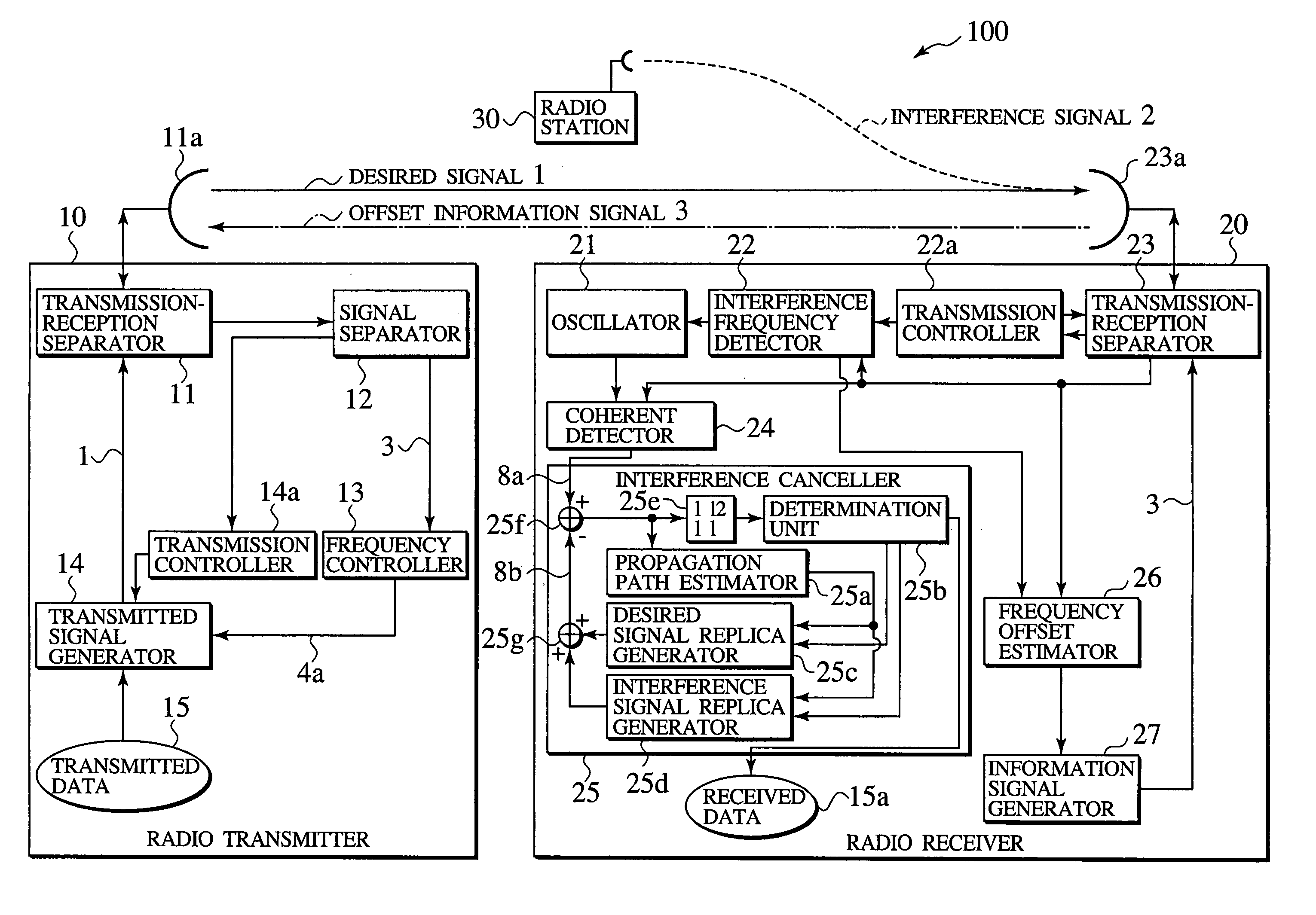
[0053]As shown in FIG. 3, a radio communication system 100 comprises a radio transmitter 10 and a radio receiver 20. The radio transmitter 10 transmits a desired signal 1 including transmitted data 15 to the radio receiver 20. The radio receiver 20 receives the desired signal 1 transmitted from the radio transmitter 10, and an interference signal 2 from a radio station 30. In the radio communication system 100, radio communication between the radio transmitter 10 and the radio receiver 20 are performed. For example, the radio communication between base stations, between access points, between the base station and access point, between the mobile station and base station, between the radio terminal and access point, between the radio stations in the adohoc network, or between the radio stations in the multihop network can be performed. In other words, the base station, the access point, the mobile station, the radio terminal, the radio st...

second embodiment

[Second Embodiment]

[0087]As shown in FIG. 5, a radio communication system 100a comprises a radio transmitter 10a and the radio receiver 20. The radio transmitter 10a comprises the antenna 11a, the transmission-reception separator 11, the signal separator 12, the transmission controller 14a, a power amplifier 161, a frequency converter 162, an oscillator 163, a phase shift calculator 164, a baseband modulator 165, and a multiplier 166. Namely, the radio transmitter 10a shown in FIG. 5 comprises the phase shift calculator 164 and the multiplier 166 in place of the frequency controller 13 of the radio transmitter 10 shown in FIG. 3, and also comprises the power amplifier 161, the frequency converter 162, the oscillator 163 and the baseband modulator 165 in place of the transmitted signal generator 14. The same reference numerals are given in FIG. 5 for the substantially same configuration as those in the radio communication system 100 shown in FIG. 3, and a part of the description is o...

third embodiment

[Third Embodiment]

[0097]As shown in FIG. 6, a radio communication system 100b comprises a radio transmitter 10b and the radio receiver 20. The radio transmitter 10b comprises the antenna 11a, the transmission-reception separator 11, the signal separator 12, the transmission controller 14a, the power amplifier 161, the frequency converter 162, the oscillator 163, and an oscillator controller 167. Namely, the radio transmitter 10b shown in FIG. 6 comprises the oscillator controller 167 in place of the frequency controller 13 of the radio transmitter 10 shown in FIG. 3, and also comprises the power amplifier 161, the frequency converter 162, the oscillator 163, and the baseband modulator 165 in place of the transmitted signal generator 14. The same reference numerals are given in FIG. 6 for the substantially same configuration as those in the radio communication systems 100 and 100a shown in FIGS. 3 and 5, and a part of the description is omitted.

[0098]The signal separator 12 inputs to...


PUM


Abstract

A radio communication system comprises: a radio receiver including an interference canceller configured to generate a replica of a received signal and remove an interference signal from the received signal, and a frequency offset estimator configured to estimate a carrier frequency offset between a carrier frequency of the interference signal and a carrier frequency of a desired signal included in the received signal; and a radio transmitter including a frequency controller configured to adjust a carrier frequency of a transmitted desired signal to the carrier frequency of the interference signal based on the carrier frequency offset received from the radio receiver.

Description

CROSS REFERENCE TO RELATED APPLICATIONS[0001]This application is based upon and claims the benefit of priority from the prior Japanese Patent Applications No. P2003-51894, filed on Feb. 27, 2003 and No. P2003-169916, filed on Jun. 13, 2003; the entire contents of which are incorporated herein by reference.BACKGROUND OF THE INVENTION[0002]1. Field of the Invention[0003]The present invention relates to a radio communication system, a radio station, and a radio communication method.[0004]2. Description of the Related Art[0005]Conventionally, with the radio communication system, technology reducing affects from interference and increasing frequency utilization efficiency has been considered, since the frequency utilization efficiency deteriorates due to a plurality of radio signals interfering with each other. For example, an interference canceller is used for such interference reduction technology. As shown in FIG. 1, an interference canceller 820 in a receiver 800 estimates the propag...

Claims


Application Information

Patent Timeline
Patent Type & Authority Patents(United States)
IPC IPC(8): H04B1/04H04B1/10H04B1/3822H04B1/40H04B7/005H04B17/24H04B17/345H04W24/00H04W52/46
CPCH04B1/10H04B1/1027H04B1/123H04W52/46
Inventor MAEDA, KOJIABURAKAWA, YUJIOTSU, TORU
Owner NTT DOCOMO INC
Why Eureka
Try Eureka