Method of manufacturing a microcoil construction

a manufacturing method and microcoil technology, applied in the direction of magnetic variable regulation, magnetic bodies, instruments, etc., can solve the problems of reducing the yield increasing the problem of coil damage, and reducing the production efficiency of the manufacturing method, so as to achieve the effect of reducing the processing step, reducing the risk of contamination, and reducing the production cos

Inactive Publication Date: 2007-05-01
IMAGE GUIDED NEUROLOGICS INC DELAWARE
View PDF11 Cites 1 Cited by
  • Summary
  • Abstract
  • Description
  • Claims
  • Application Information

AI Technical Summary

Benefits of technology

[0010]What is needed is a microcoil that can be manufactured more easily and which results in a more uniform microcoil with more consistent quality. What is also needed is a microcoil made by attaching a conductor onto an insulating film and configuring the film to form a winding or multiple windings. The manufacturing process of the microcoil requires minimal processing steps and minimal exposure to handling damage during processing. The process of manufacturing the microcoil is also conducive to tight quality control standards yet it is easily adapted to accommodate product design changes. The novel manufacturing process is capable of producing a novel microcoil that is extremely small and inexpensive, with a high manufacturing yield.
[0012]In a further embodiment of the invention, the conductor is deposited as a trace onto the film using lithography and sputtering deposition techniques. The shape of the resulting microcoils is easily controlled by changing the mask pattern for the conducting trace deposited on the film. The electrical properties of the trace of conducting material are easily controlled by varying the trace material, and the width / thickness of the trace.

Problems solved by technology

Handling windings in the manufacturing process can cause damage to the fragile windings resulting in manufacturing yield loss.
The trend of smaller devices only increases this problem.
These coils are more easily damaged.
While these conventional approaches to the manufacture of windings and microcoils result in functioning microcoils, the process is time consuming with several steps.
Manufacturing yield is a problem due to the handling necessary in the conventional process, and consistent quality control is difficult.

Method used


Image

  • Method of manufacturing a microcoil construction
  • Method of manufacturing a microcoil construction
  • Method of manufacturing a microcoil construction

Examples


Embodiment Construction

[0024]A catheter 100 is shown in FIG. 6, is used to probe areas of interest inside a patient. The distal end 101 of the catheter 100 can be inserted by controls at its proximal end 102. In order to image the area of interest, and potentially steer the distal end 101 of the catheter to the desired location, it is helpful to include an MR microcoil 60 at the distal end 101 of the catheter 100. The microcoil 60 uses magnetic resonance imaging techniques to characterize the tissue in its immediate vicinity. Signals from the microcoil 60 are sent along a length 104 of the catheter 101 through an electrical channel 103 to the proximal end 102 of the catheter where they can be used by the surgeon to indicate where the distal end 101 of the catheter is, and what types of tissue are near the distal end 101.

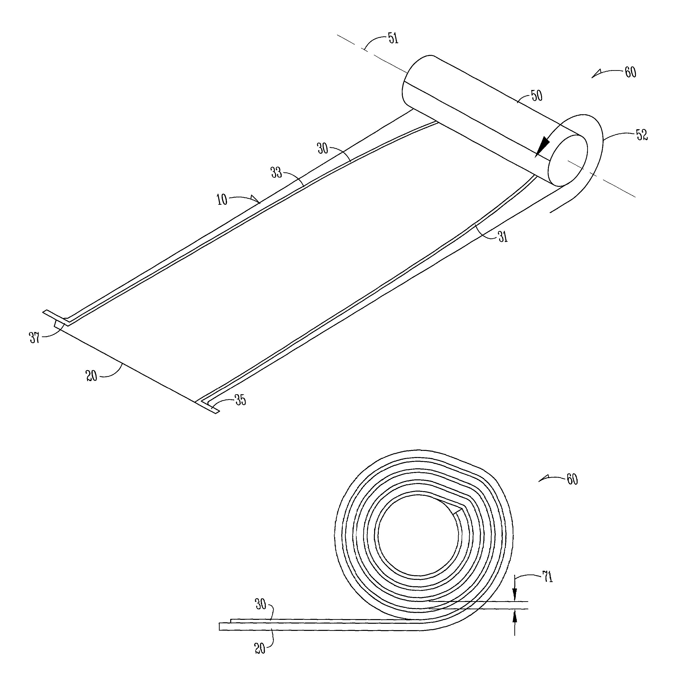
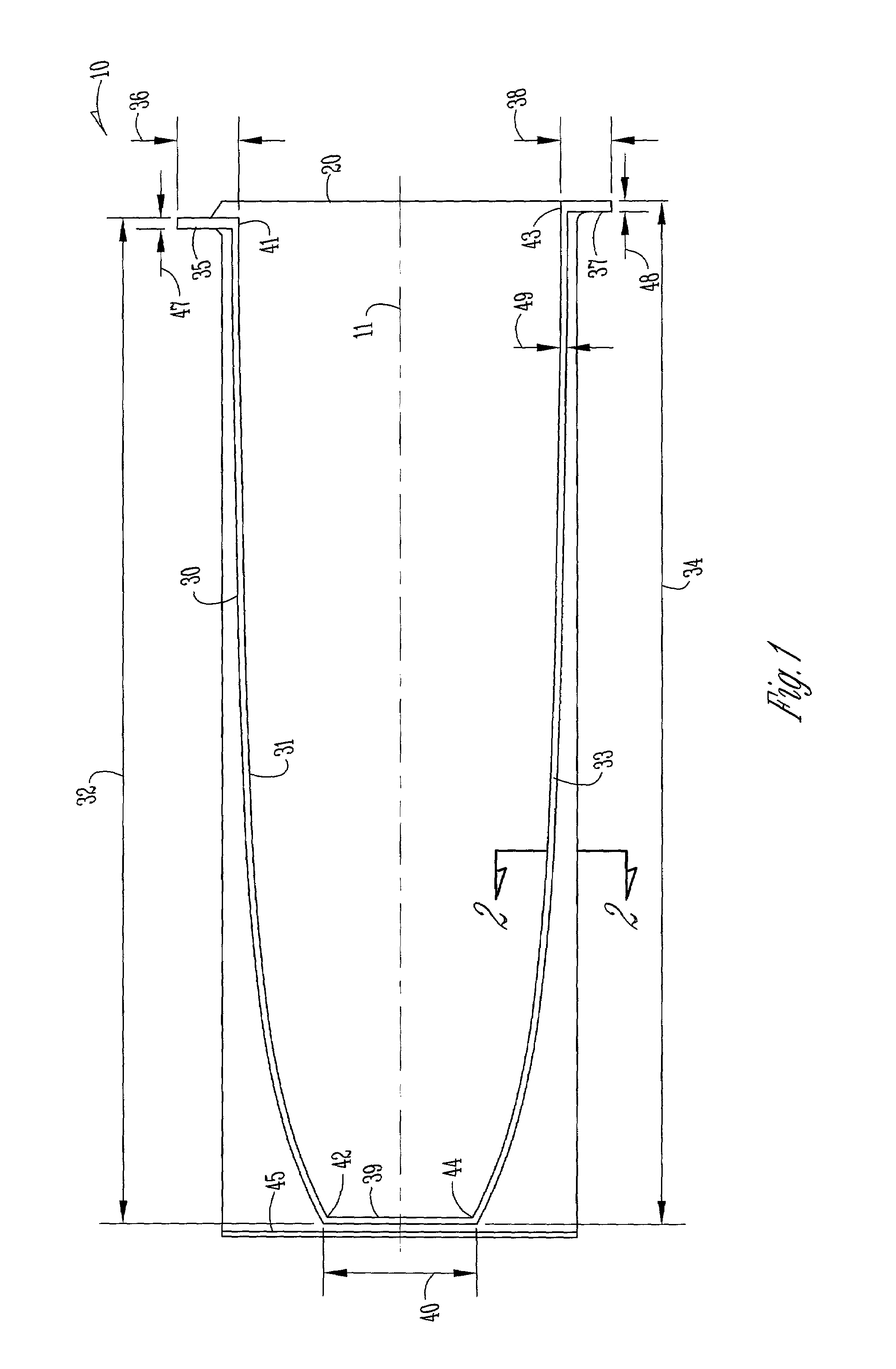
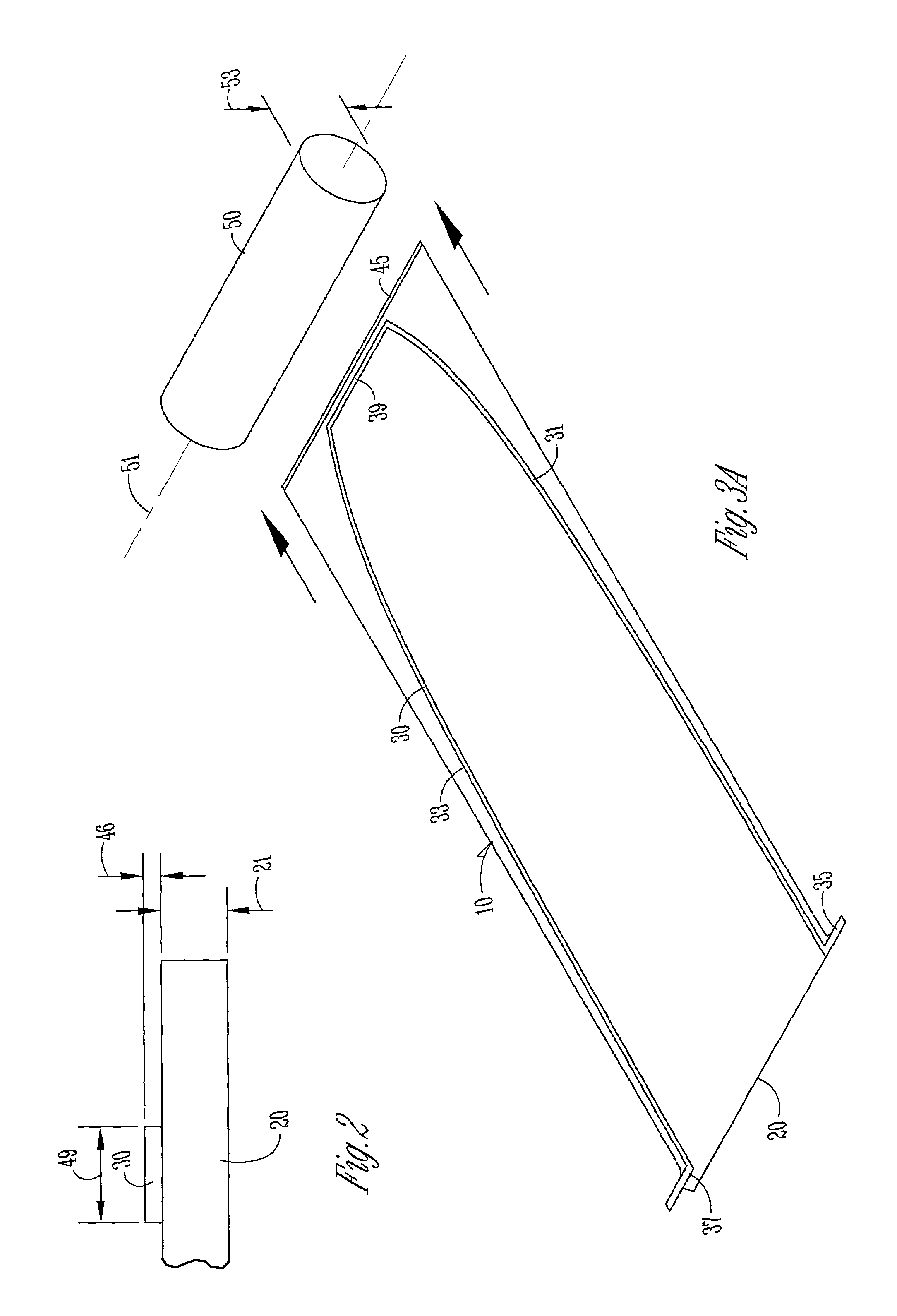
[0025]A microcoil 60 as shown in FIG. 5 is manufactured by rolling a trace unit 10 as shown in FIG. 1 in such a way as to form at least one winding 70. A preferred embodiment of the microc...


PUM

PropertyMeasurementUnit
angleaaaaaaaaaa
conductiveaaaaaaaaaa
conductingaaaaaaaaaa

Abstract

A microcoil is manufactured by rolling a trace unit in such a way as to form at least one winding. The trace unit is comprised of a conductive trace attached to a flexible insulating film. A preferred embodiment of the microcoil contains both a first winding and a second winding electrically connected and spaced apart by a joining portion. The microcoil may be used for internal magnetic resonance imaging of patient by attaching the microcoil to a catheter.

Description

BACKGROUND OF THE INVENTION[0001]1. Field of the Invention[0002]This invention relates to microcoils and their construction. Specifically, this invention relates to microcoils for use in medical devices used to obtain a magnetic resonance image of a region within a natural organism or patient (such as within a human) or elsewhere.[0003]2. Background of the Invention[0004]The use of magnetic resonance medical devices provides enhanced imaging within the region of interest and can be used for various internal procedures including targeted drug delivery. The term microcoil or MR microcoil is used to denote a magnetic resonance device used for imaging internally from a patient. This term is in contrast to MR coils that are conventionally used externally to the body for MR imaging purposes. A microcoil may contain one winding of electrical conductor, or multiple windings that are spaced a distance apart from each other. Typically multiple windings are joined together at a predetermined s...

Claims


Application Information

Patent Timeline
Patent Type & Authority Patents(United States)
IPC IPC(8): H05K3/34H01F5/00A61B5/055G01R33/28
CPCG01R33/285A61B5/055Y10T29/49144Y10T29/49071Y10T29/49073Y10T29/49117Y10T29/49124
Inventor MILLS, GERALD W
Owner IMAGE GUIDED NEUROLOGICS INC DELAWARE
Why Eureka
Try Eureka