Energy absorbing vehicle fender

a technology for vehicles and fenders, applied in the field of vehicle fenders, can solve problems such as the area of vehicles that is difficult to maintain, and achieve the effect of sufficient stability

Inactive Publication Date: 2007-05-01
SABIC INNOVATIVE PLASTICS IP BV
View PDF6 Cites 10 Cited by
  • Summary
  • Abstract
  • Description
  • Claims
  • Application Information

AI Technical Summary

Benefits of technology

[0006]Typical fenders have a relatively short distance between the upped edge of the fender and attachment of the flange to the rigid support member or so-called shotgun. In order to comply with upcoming pedestrian safety requirements, in particular, proposed head impact requirements, this area of the vehicle presents a problem. In order to comply with these requirements, the structure of the fender and the support of the fender are desirable altered so that an intrusion space is created so that deceleration of an object upon impact with the fender remains relatively low so that the forces of impact are reduced.
[0007]According to an embodiment, the intrusion distance for a plastic fender is desirably increased by lowering the position of the rigid support member or shotgun. According to an embodiment, the dimensional stability of the fender is retained while providing for a desirable crushing of the fender upon impact. The reaction of the fender to an intrusion force is desirably provided at the proper level so as to absorb the impact energy force in the available crush distance. According to an embodiment, an integrated solution is incorporated into a thermoplastic fender that is adaptable for pedestrian safety. According to an embodiment, the crushable features of the fender require no additional parts and no secondary operations.
[0008]According to an embodiment, the attachment flange has a vertically aligned section that can be tuned to reduce the forces of impact from a top frontal position when crushed by an object but is provided with sufficient stiffness in the other directions to provide dimensional stability.
[0010]Variations are set forth herein and it is contemplated that multiple design features of different shapes can be integrated into the vertically aligned section of the attachment flange so that a desired and sufficient stability may be obtained.

Problems solved by technology

In order to comply with upcoming pedestrian safety requirements, in particular, proposed head impact requirements, this area of the vehicle presents a problem.

Method used


Image

  • Energy absorbing vehicle fender
  • Energy absorbing vehicle fender
  • Energy absorbing vehicle fender

Examples


Embodiment Construction

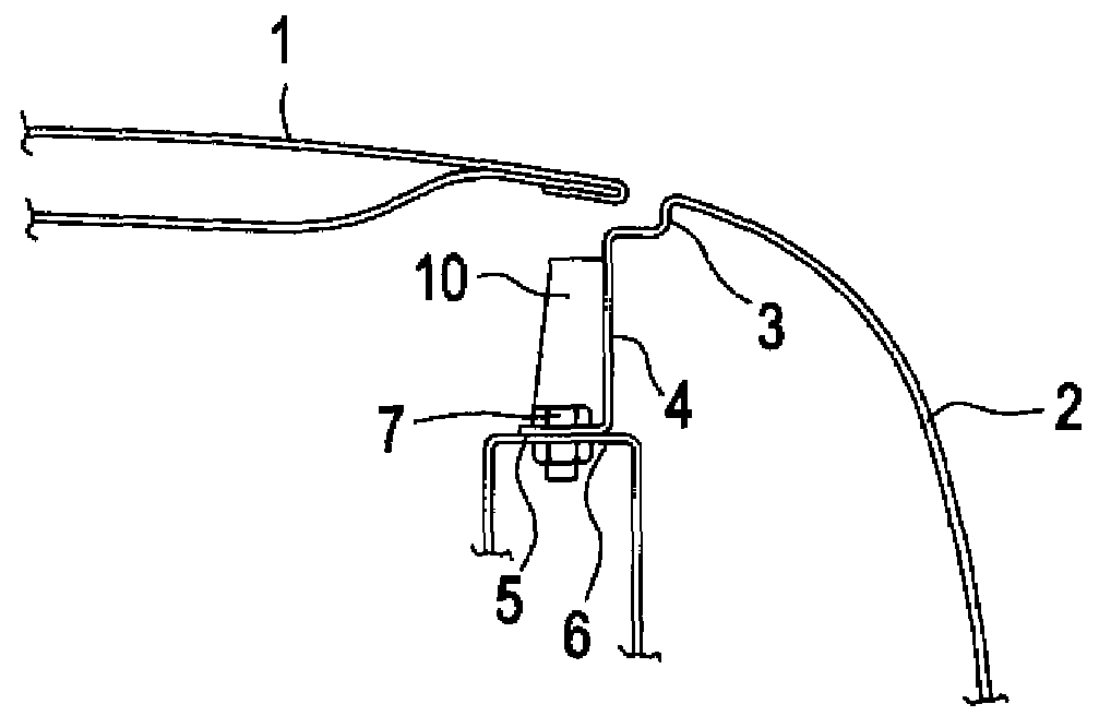
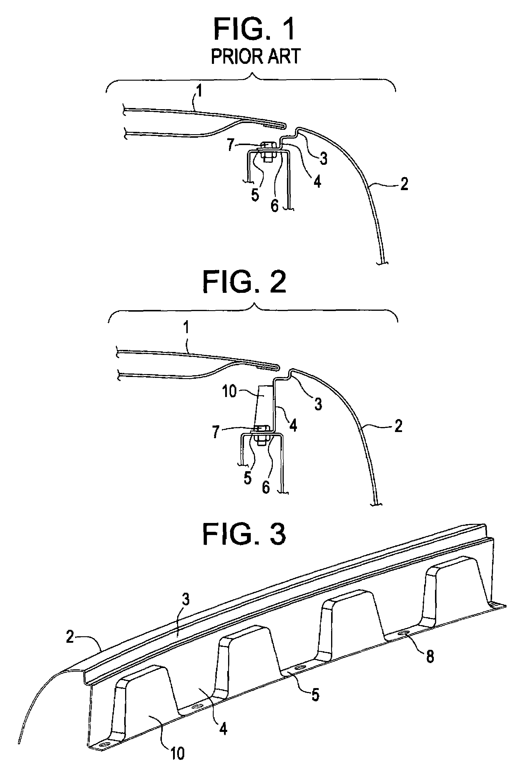
[0026]FIG. 1 shows partial cross sectional view of a typical prior art mounting of a metal fender 2, which is fixedly secured to support member 6 with a nut and bolt shown at 7. A hood is shown at reference number 1. The fender 2 includes a flanged portion having a vertically depending section 4 joined to a horizontally aligned section 5. A recess portion 3 extends downwardly into the forward compartment from the exterior surface and provides for the seating of the hood 1 when the hood is in a closed position. The recess portion 3 includes an exterior rim at its junction with the exterior portion of the fender 2. As illustrated in FIG. 1, the height of vertically depending section 4 is relatively short so that the distance between the top of fender 2 and the rigid support member 6 is a relatively short distance so that very little space is provided for intrusion of an object during impact before the rigid support member 6 is contacted.

[0027]FIG. 2 illustrates an embodiment where the...


PUM


Abstract

A fender for absorbing forces generated from an impact includes a depending attachment flange which comprises a vertically aligned section depending from an exterior portion of the fender and a horizontally aligned section depending from the vertically aligned section adapted for mounting to a vehicle wherein the vertically aligned section includes a plurality of contoured portions for enhancing the stiffness of the vertically aligned section.

Description

CROSS REFERENCE TO RELATED APPLICATIONS[0001]This application is a continuation in part of U.S. patent application PCT / US04 / 29279 and claims rights of priority under 35 U.S.C. 19 from U.S. patent application Ser. No. PCT / US04 / 29279 filed on Sep. 3, 2004 and U.S. Provisional Application Ser. No. 60 / 500633 filed on Sep. 5, 2003, which are incorporated herein by reference in its entirety.FIELD OF INVENTION[0002]The invention relates to a vehicle fender of the type that is adaptable for pedestrian protection.BACKGROUND OF THE INVENTION[0003]Future legislation in Japan and European countries may require an energy absorbent design for vehicle fender systems to help protect a pedestrian's head and body from impact with an automotive fender.[0004]Typically, a metal fender is attached to the body of vehicle through a rigid support member sometimes referred to as a shotgun or apron panel. This rigid member, which extends lengthwise of the vehicle, is typically connected to the frame of the au...

Claims


Application Information

Patent Timeline
Patent Type & Authority Patents(United States)
IPC IPC(8): B62D25/16B60R21/34
CPCB60R21/34B62D25/105B62D25/16B62D25/163B60R2021/343
Inventor MARIJNISSEN, KEESGILSING, ROY
Owner SABIC INNOVATIVE PLASTICS IP BV
Why Eureka
Try Eureka