Biometric identity verifiers and methods

a biometric identity and verification technology, applied in the field of optical fingerprint identity verification hardware systems, can solve the problems of limiting commercial applications, increasing the cost of manufacturing the sensor module, etc., and achieves the effect of accurately positioning the image for successful image capture and increasing the accuracy of identity verification

Active Publication Date: 2007-05-01
CHIAO TUNG HLDG LLC
View PDF11 Cites 43 Cited by
  • Summary
  • Abstract
  • Description
  • Claims
  • Application Information

AI Technical Summary

Benefits of technology

[0010]The present invention provides for a biometric identity verifier. The biometric identity verifier comprises an optical fingerprint sensor coupled to an ID (identification) card reader. In one embodiment of the present invention, the optical fingerprint sensor includes a light source on a PCB assembly, a diffuser that receives light from the light source, a right angle prism that receives light from the diffuser, a collimating lens that receives light from the prism, a first mirror that receives light from the collimating lens, a second mirror that receives light from the first mirror, a third mirror that receives light from the second mirror, an imaging lens that receives light from the third mirror, and an image sensor on the same PCB assembly as the light source that receives light from the imaging lens. In one embodiment of the present invention, an ID (identification) card reader reads an ID card that contains biometric information about the user, and compares the biometric information on the card with the fingerprint of the user captured by the optical fingerprint sensor. In another embodiment of the present invention, the biometric identity verifier includes additional biometric sensors, such as a microphone for voice recognition, and a camera for facial or iris recognition. Advantageously, the integration of additional biometric sensors in the biometric identity verifier increases the accuracy of identity verification. In another embodiment of the present invention, the biometric identity verifier includes an LCD to display the facial, iris, or fingerprint image, providing feedback so the user can more accurately position themselves for successful image capture. The biometric identity verifier described in the present invention can be advantageously embedded in consumer and industrial devices to provide identity verification, including computers, telephones, personal digital assistants, automobiles, and industrial machinery.

Problems solved by technology

As a consequence of the characteristic optical path described above, existing optical fingerprint sensors have the following drawbacks: (1) the sensor module has a large volume thereby limiting the range of commercial applications, (2) the non-planar orientation of the light source and the imaging sensor increases the cost to manufacture the sensor module and also limits commercial applications, and (3) the fingerprint image captured by the image sensor is compressed along one direction necessitating software correction of the fingerprint image which increases the cost to manufacture the sensor module and further limits commercial applications.
The problem with these approaches is that they necessitate a bulky and expensive sensor module.
The problem with this approach is that the fingerprint image quality suffers due to the optical imperfections of the grating.

Method used


Image

  • Biometric identity verifiers and methods
  • Biometric identity verifiers and methods
  • Biometric identity verifiers and methods

Examples


Embodiment Construction

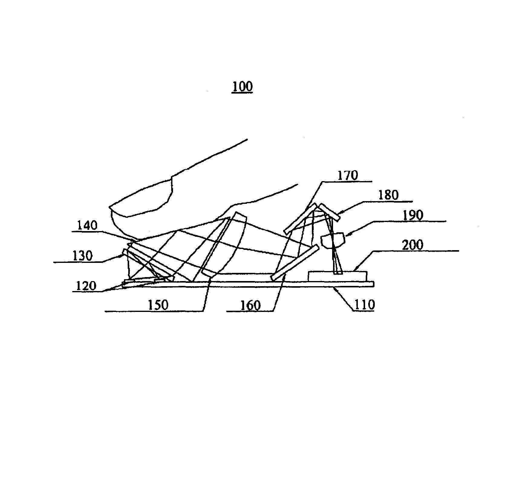
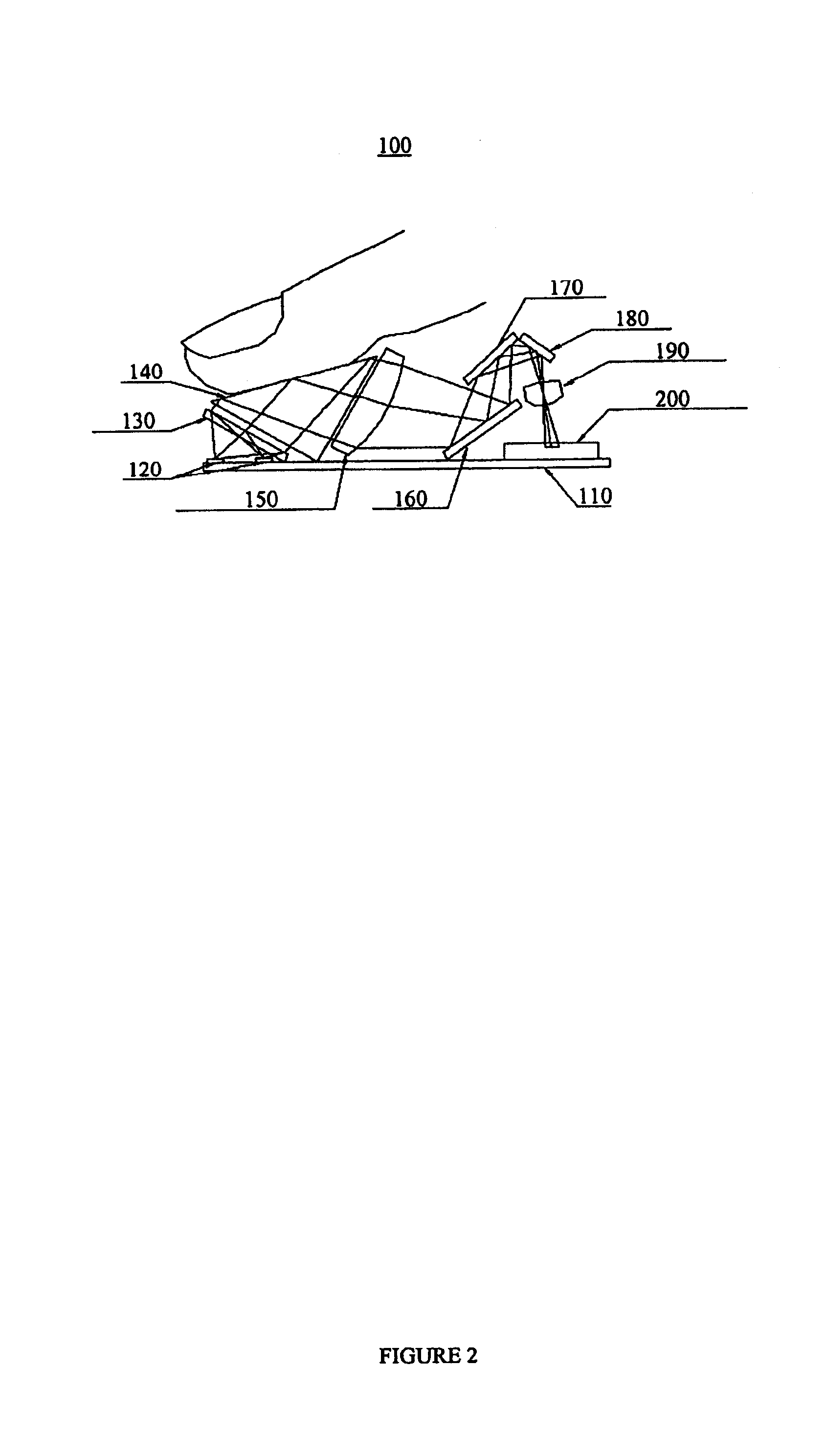
[0023]FIG. 2 illustrates the optical path through the components of an optical fingerprint sensor 100 in accordance with the present invention. In the preferred embodiment of the present invention, the components comprise a PCB assembly 110, a light source 120, a diffuser130, a right angle prism 140, a collimating lens 150, a first mirror 160, a second mirror 170, a third mirror 180, an imaging lens 190, and an image sensor 200.

[0024]Light rays are emitted from a light source 120 located on the PCB assembly 110 comprising, for example, a number of LEDs.

[0025]The light rays then impinge upon a diffuser 130 that changes the direction of the light rays to create a uniform illumination of the right angle prism 140.

[0026]The light rays entering the right angle prism 140 then impinge upon the upper surface of the right angle prism 140 where a finger is placed. In the preferred embodiment of the present invention, it is ergonomically beneficial for the upper surface of the right angle pris...


PUM


Abstract

For use in verifying the identity of a user, an identity verifier comprising an optical fingerprint sensor coupled to an ID (identification) card reader. In one embodiment of the present invention, the optical fingerprint sensor includes a light source on a PCB assembly, a diffuser that receives light from the light source, a right angle prism that receives light from the diffuser, a collimating lens that receives light from the prism, a first mirror that receives light from the collimating lens, a second mirror that receives light from the first mirror, a third mirror that receives light from the second mirror, an imaging lens that receives light from the third mirror, and an image sensor on the same PCB assembly as the light source that receives light from the imaging lens. In one embodiment of the present invention, an ID (identification) card reader reads an ID card that contains biometric information about the user, and compares the biometric information on the card with the fingerprint of the user captured by the optical fingerprint sensor captured by the optical fingerprint sensor.

Description

CROSS REFERENCE TO RELATED APPLICATIONS[0001]This application relates to a co-pending U.S. patent application Ser. No. 10 / 100,689, filed on Mar. 14, 2002, entitled “Compact Optical Fingerprint Sensor and Method” by Chen Feng, owned by the assignee of this application and incorporated herein by reference.BACKGROUND INFORMATION[0002]1. Field of the Invention[0003]The present invention is directed in general to biometric identity verifier devices, and more specifically to optical fingerprint identity verifier hardware systems.[0004]2. Description of Related Art[0005]Existing optical fingerprint sensors generally use a right angle prism to capture the fingerprint image. The characteristic optical path in such sensors is illustrated in FIG. 1. Collimated light rays from a light source pass through one side of the prism. These light rays then travels to the top of the prism where a finger is placed. If a light ray impinges on a location where the finger is not in direct contact with the t...

Claims


Application Information

Patent Timeline
Patent Type & Authority Patents(United States)
IPC IPC(8): G06K9/74G06K9/00
CPCG06K9/00046G06V40/1324
Inventor FENG, CHEN
Owner CHIAO TUNG HLDG LLC
Why Eureka
Try Eureka