GFCI with miswire lockout

a technology of miswire lockout and protection device, which is applied in the direction of earth fault current operation switch, emergency protective arrangement for limiting excess voltage/current, protective switch details, etc., can solve the problem of inability to prevent the problem of defective solenoid driving device inherently more difficult, device does not provide ground fault protection, etc. problem, to achieve the effect of eliminating hazardous conditions

Inactive Publication Date: 2007-05-01
PASS SEYMOUR
View PDF41 Cites 70 Cited by
  • Summary
  • Abstract
  • Description
  • Claims
  • Application Information

AI Technical Summary

Benefits of technology

[0013]The present invention address the needs described above. The present invention provides a multi-shot miswire detection circuit. Further, the present invention eliminates hazardous conditions at the receptacle outlets when the device is tripped.

Problems solved by technology

Historical problems with these protective devices include the possibility of line / load miswiring in the field by an installer or the eventual failure of the solenoid driving device, typically a silicon controlled rectifier, which causes the interrupter device to become inoperable while electrical power is still present, even under hazardous ground fault conditions.
Preventing the problems associated with a defective solenoid driving device is inherently more difficult.
The device is not providing ground fault protection when the reset button fails to pop out.
However, this approach has several drawbacks.
Of course, users routinely ignore the instructions printed on the cover of GFCI devices.
If the device fails, the user is not aware that the device is not affording any protection.
On the other hand, even if the user does press the button and discover that the device has failed, it may be some time before the user replaces the device.
Another drawback of the standard devices relates to the fact that a line-load miswire condition is often not tested by the test button.
When a device is miswired, it may not protect the user from a fault condition even if it is functioning properly.
The hazard will be present at the receptacle outlets even if the device is tripped.
However, since the load terminals and the user load terminals are still connected, the device fails to protect the user.
In this case, the test and reset buttons may operate normally, giving the user a false sense of security.
Further, if the device is experiencing an internal fault such that the device is not operating properly, the device will likewise, not reset.
One drawback to this condition is that it provides the user a disincentive to test.
In other words, the user will feel inconvenienced if the device does not work after the test button is pushed.
Further, this approach fails to address the scenario described above, when users fail to routinely use the test button.

Method used


Image

  • GFCI with miswire lockout
  • GFCI with miswire lockout
  • GFCI with miswire lockout

Examples


Embodiment Construction

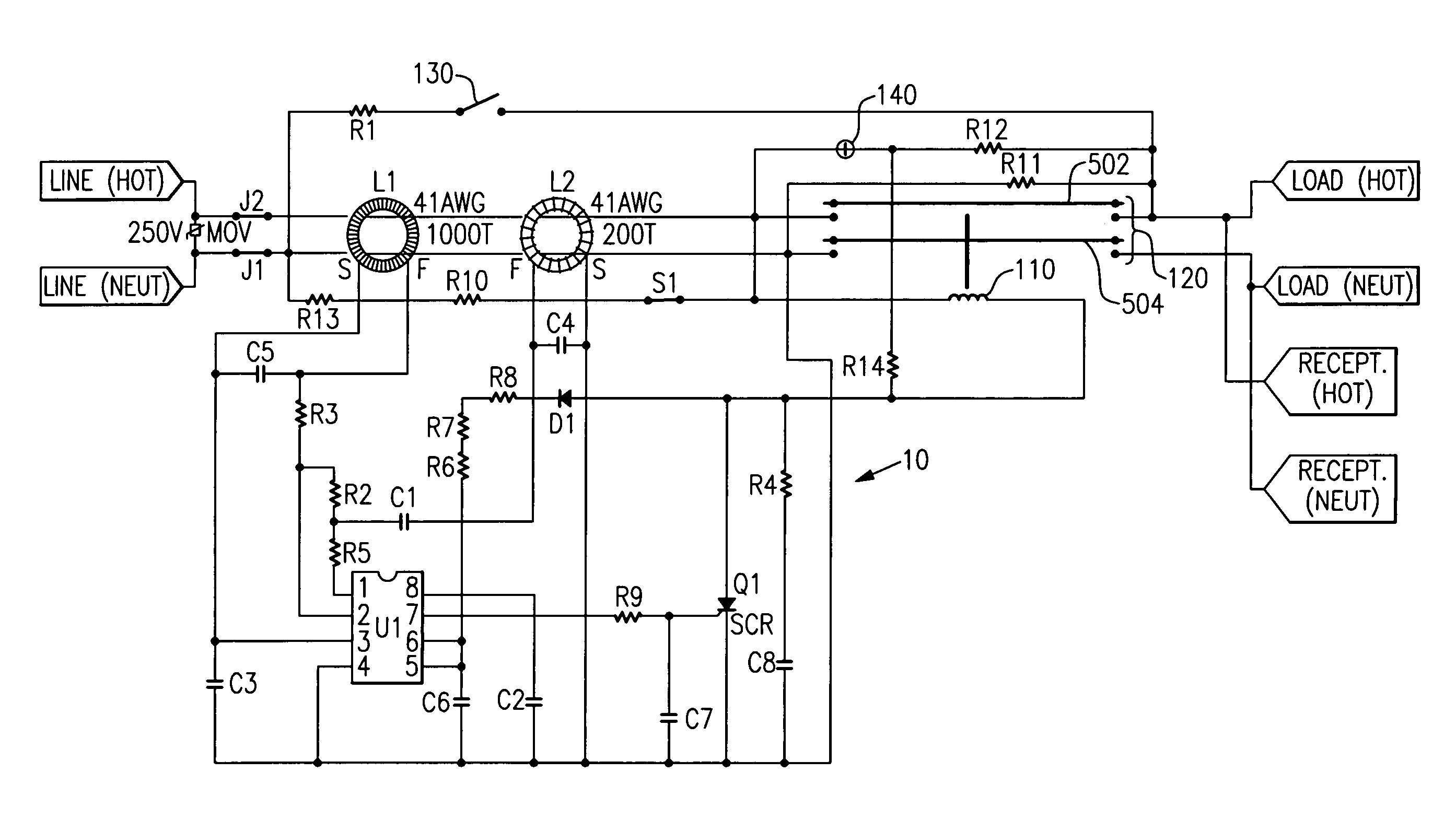
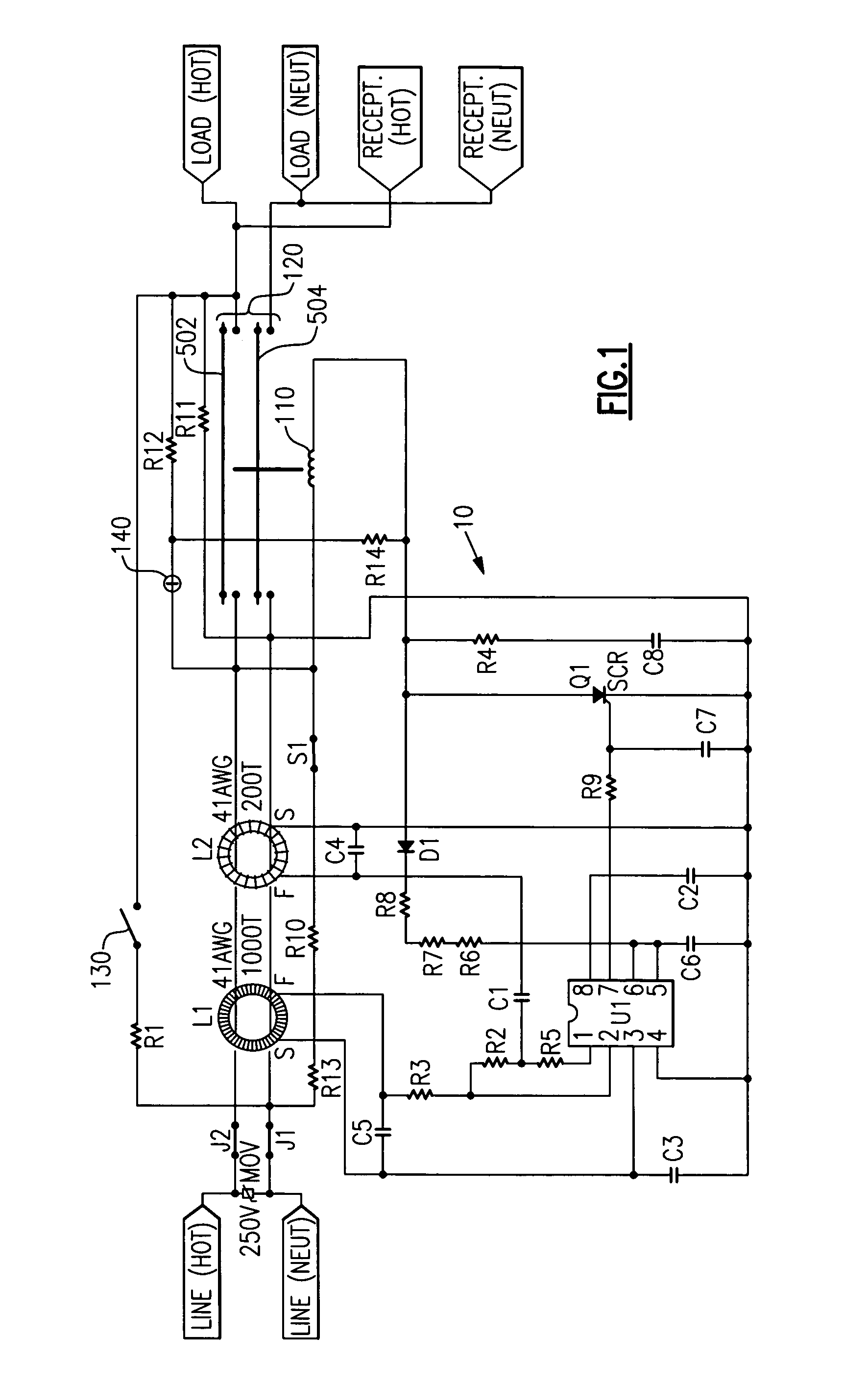
[0036]Reference will now be made in detail to the present exemplary embodiments of the invention, examples of which are illustrated in the accompanying drawings. Wherever possible, the same reference numbers will be used throughout the drawings to refer to the same or like parts. An exemplary embodiment of the ground fault circuit interrupter (GFCI) of the present invention is shown in FIG. 1, and is designated generally throughout by reference numeral 10.

[0037]As embodied herein and depicted FIG. 1, a GFCI circuit in accordance with one embodiment is shown. When a differential transformer L1 senses unequal amounts of current flowing in the hot and neutral conductors due to a ground fault condition, device 10 causes a breaker coil 110 to activate, opening circuit interrupting mechanism 120. As shown, circuit interrupting mechanism 120 includes hot and neutral bus bars 502, 504. The circuit interrupting mechanism 120 is configured to establish and break connectivity between the hot a...


PUM


Abstract

The present invention is directed to an electrical wiring protection device that includes a housing assembly having at least one line terminal and at least one load terminal partially disposed therein. A first conductive path is electrically coupled to the at least one line terminal. A second conductive path is electrically coupled to the at least one load terminal, the second conductive path being connected to the first conductive path in a reset state. A fault detection circuit is coupled to the first conductive path. The fault detection circuit is configured to generate a fault detection signal in response to detecting at least one fault condition. A wiring state detection circuit is coupled to the first conductive path. The wiring state detection circuit selectively provides a wiring state detection signal when the at least one line terminal is coupled to a source of AC power, and not providing the wiring state detection signal otherwise. An actuator assembly is configured to provide an actuation stimulus in response to the fault detection signal or the wiring state detection signal. A circuit interrupter is coupled to the actuator assembly. The circuit interrupter is configured to disconnect the first conductive path and the second conductive path in response to the actuation stimulus.

Description

CROSS-REFERENCE TO RELATED APPLICATIONS[0001]This is a continuation-in-part of U.S. patent application Ser. No. 10 / 884,304 filed on Jul. 2, 2004 now U.S. Pat. No. 7,133,266 and U.S. patent application Ser. No. 10 / 942,633 filed on Sep. 16, 2004 now U.S. Pat. No. 7,173,799, U.S. patent application Ser. No. 10 / 884,304 is a continuation of U.S. patent application Ser. No. 09 / 971,525 filed on Oct. 5, 2001 now U.S. Pat. No. 6,856,498, which is a continuation of U.S. patent Ser. No. 09 / 718,003 filed Nov. 21, 2000 now U.S. Pat. No. 6,522,510, the contents of which are relied upon and incorporated herein by reference in its entirety, and the benefit of priority under 35 U.S.C. §120 is hereby claimed.BACKGROUND OF THE INVENTION[0002]1. Field of the Invention[0003]The present invention relates generally to protection devices, and particularly to protection devices having miswire protection.[0004]2. Technical Background[0005]Protective devices such as ground fault circuit interrupters (GFCIs) a...

Claims


Application Information

Patent Timeline
Patent Type & Authority Patents(United States)
IPC IPC(8): H02H9/08
CPCH01H83/04H02H3/338H01H2071/044
Inventor FINLAY, SR., DAVID A.PACKARD, THOMAS N.WEEKS, RICHARD
Owner PASS SEYMOUR
Why Eureka
Try Eureka