
Quadrature modulation transmitter

a transmitter and quadrilateral technology, applied in the field of quadrilateral modulation transmitters, can solve the problems of high power consumption, increased number of parts used in an outside of the chip, and increased number of parts, so as to reduce power consumption and simplify the circuit structure

Active Publication Date: 2007-05-01
UNILOC 2017 LLC
View PDF5 Cites 4 Cited by
  • Summary
  • Abstract
  • Description
  • Claims
  • Application Information

AI Technical Summary

Benefits of technology

[0014]It is, therefore, an object of the present invention to provide a quadrature modulation transmitter which is capable of solving several problems of the conventional transmitter while performing the same function as the heterodyne transmitter or the digital IF transmitter, in which a circuit structure is simplified and power consumption is reduced compared with the conventional structure.

Problems solved by technology

However, since the circuit structure of the heterodyne transmitter is complicated, the power consumption is high and the number of parts used in an outside of the chip is increased.
Therefore, the heterodyne transmitter has a drawback in that a large number of parts are required and the power consumption is increased.
However, the direct conversion transmitter has several problems, such as a DC offset and a generation of quadrature clocks in the RF frequency.
However, to processing of even the intermediate frequency signals in the digital domain is considerably complicated and digital circuits operating at a high speed are required.
As a result, the power consumption of the digital IF transmitter is similar to that of the heterodyne transmitter and the implementation of the digital IF transmitter becomes considerably complicated in the digital signal processing domain.

Method used


Image

  • Quadrature modulation transmitter
  • Quadrature modulation transmitter
  • Quadrature modulation transmitter

Examples


Embodiment Construction

[0028]Hereinafter, a detailed description of the preferred embodiments will be made with reference the accompanying drawings.

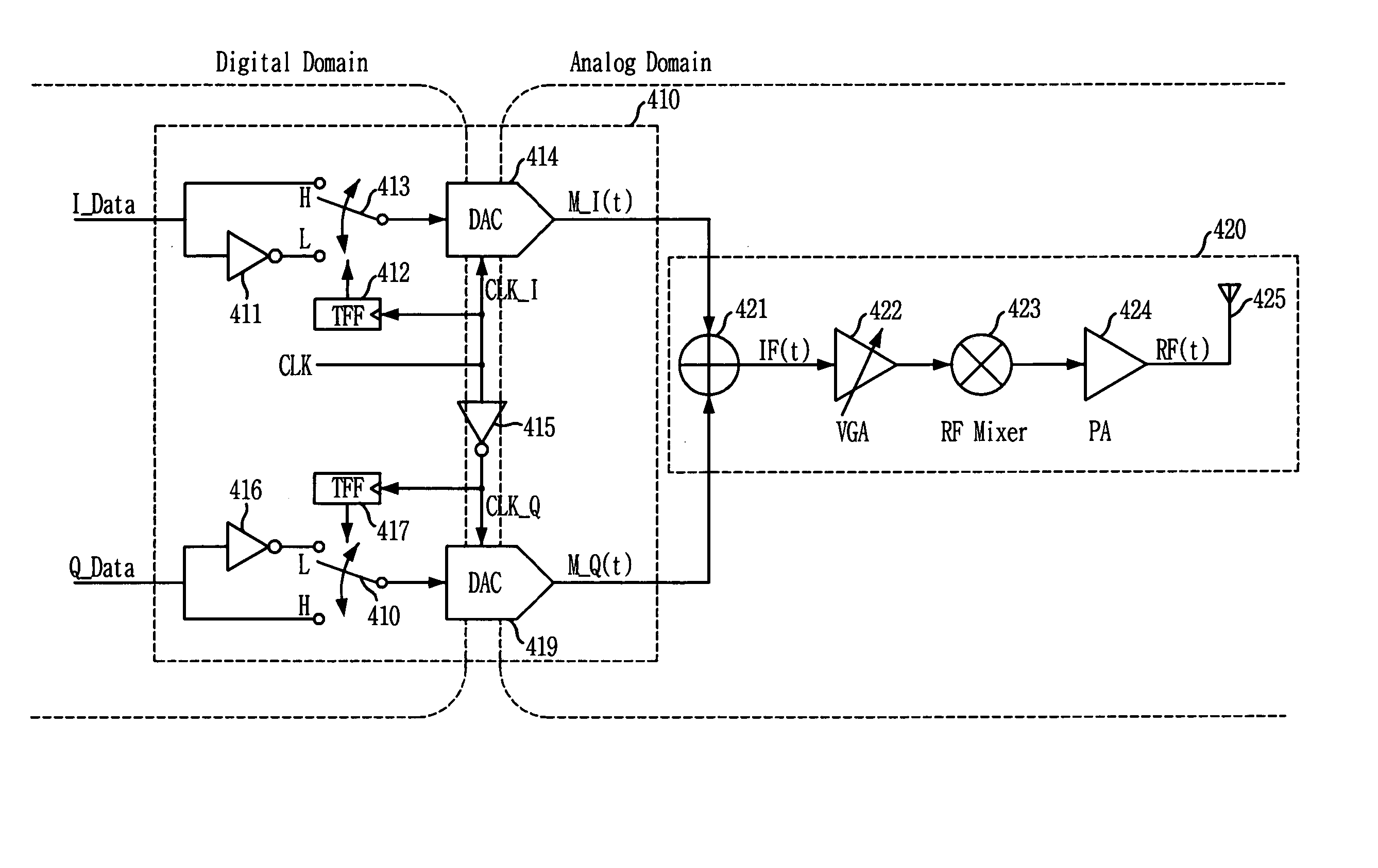
[0029]FIG. 4 is a block diagram of a quadrature modulation transmitter including a digital processing block 410 and an analog processing block 420 in accordance with an embodiment of the present invention.

[0030]Referring to FIG. 4, the digital processing block 410 receives an I-channel data I_Data, a Q-channel data Q_Data and a clock signal CLK, modulates the I-channel data I_Data or an inverted I-channel data into a first analog signal according to a switching of an I-clock signal CLK_I that is a signal identical to the clock signal CLK, and modulates the Q-channel data Q_Data or an inverted Q-channel data into a second analog signal according to a switching of the Q-clock signal CLK_Q that is an inverted clock signal CLK. Hereinafter, the digital processing block 410 will be described in detail with reference to FIG. 4.

[0031]Referring to FIG. 4, a first inve...


PUM


Abstract

There is provided a quadrature modulation transmitter which is capable of solving several problems of the conventional transmitter while performing the same function as the heterodyne transmitter or the digital IF transmitter, in which a circuit structure is simplified and a power consumption is reduced compared with the conventional transmitter. The quadrature modulation transmitter includes: a digital processing block for receiving an I-channel data, a Q-channel data and a clock signal, modulating the I-channel data or an inverted I-channel data into a first analog signal by means of an I-channel DAC according to a switching of an I-clock signal identical to the clock signal, and modulating the Q-channel data and an inverted Q-channel data into a second analog signal by means of a Q-channel DAC according to a switching of a Q-clock signal, the Q-clock signal being an inverted clock signal; and an analog processing block for receiving the first and second analog signals from the digital processing block, adding the first and second analog signals, converting the added signal into an RF domain signal through a mixing operation, and amplifying and transmitting the RF domain signal.

Description

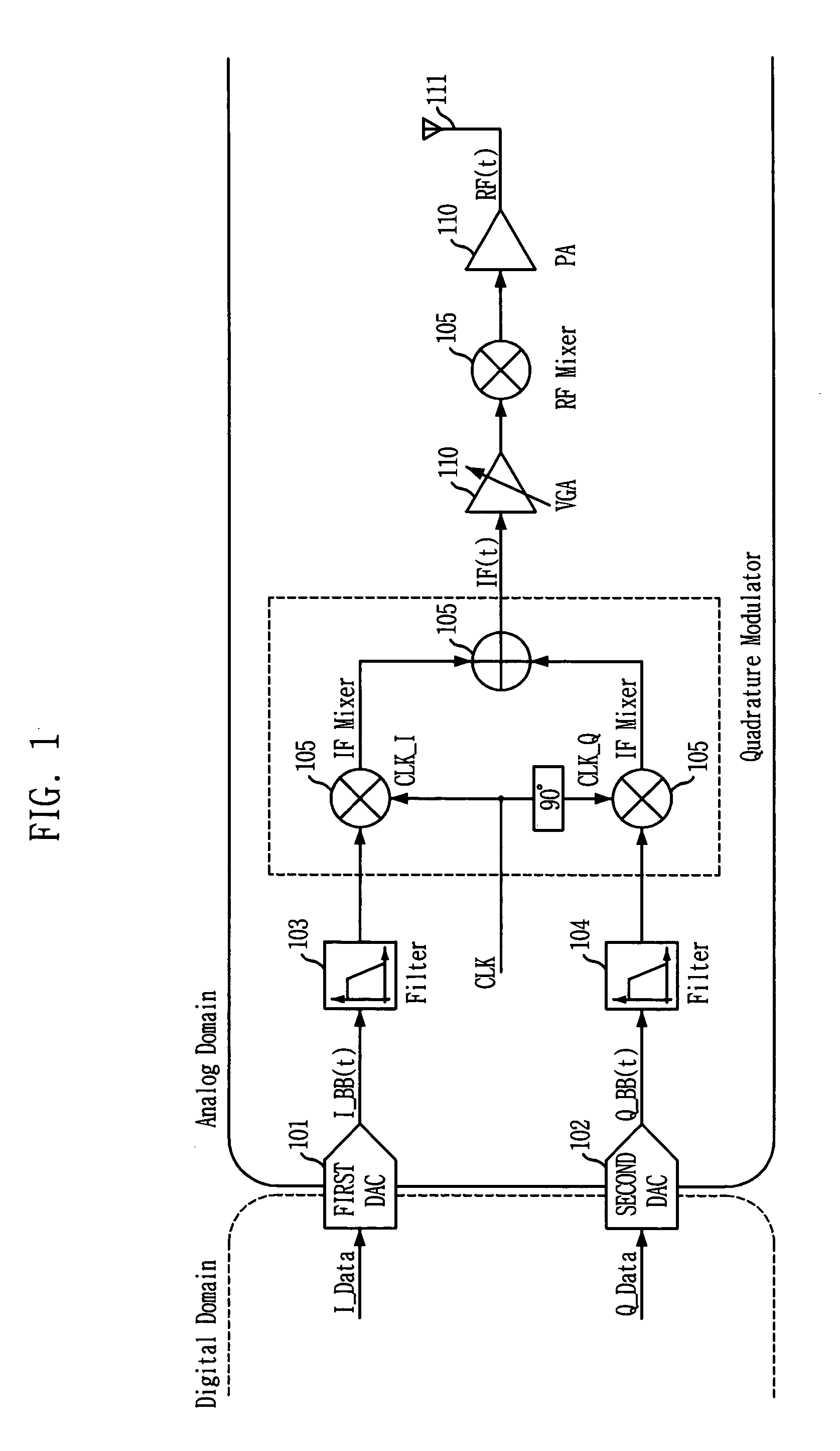
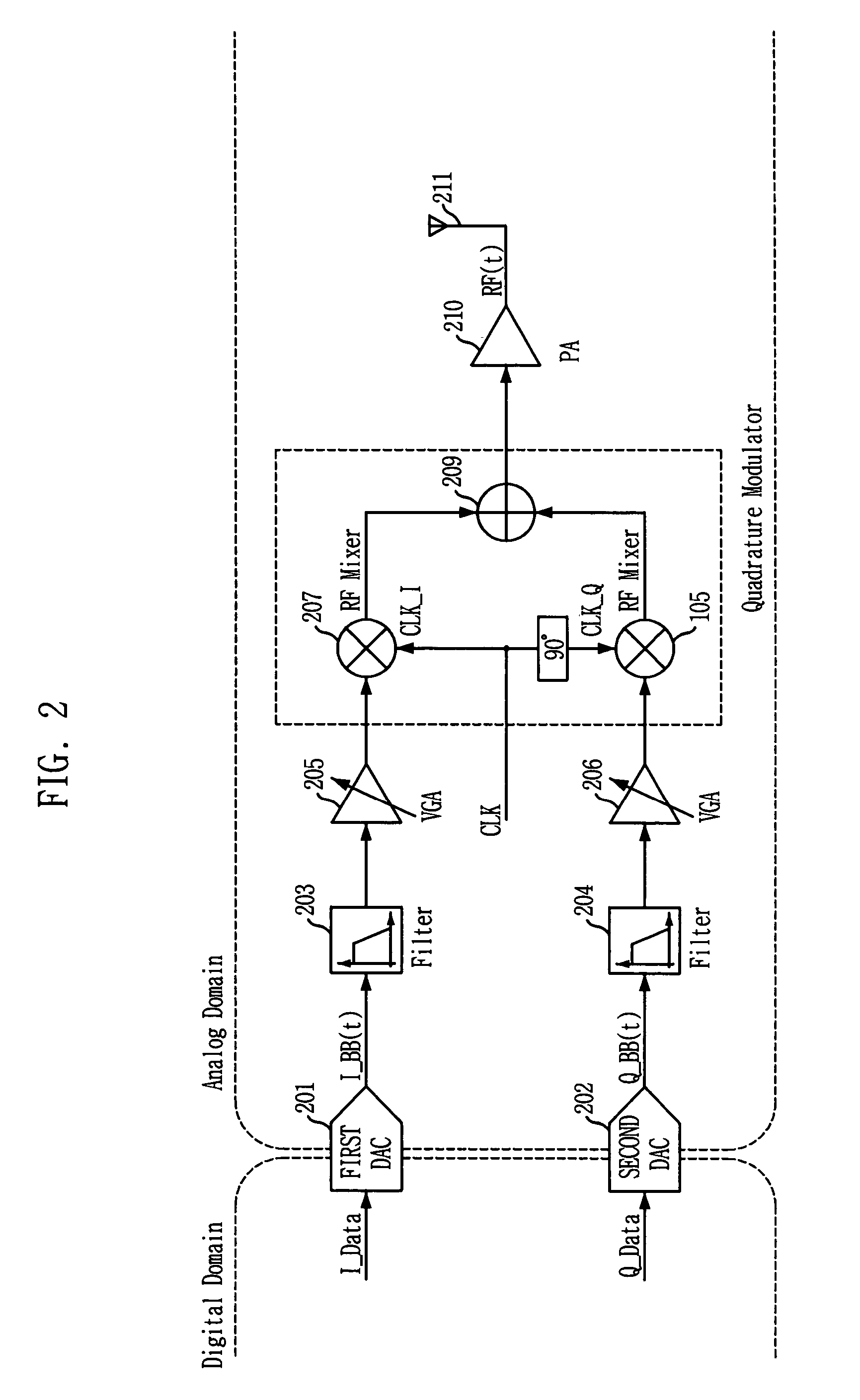
FIELD OF THE INVENTION[0001]The present invention relates to a quadrature modulation transmitter; and, more particularly, to a quadrature modulation transmitter which performs a quadrature modulation in a transmission block of a mobile communication system.DESCRIPTION OF THE PRIOR ART[0002]PCS, CDMA2000, GSM and WCDMA have been ever used as typical mobile communication systems. A structure of a transmission block used in these mobile communication systems is provided with a heterodyne system, a direct conversion system, a digital IF system, and the like. The heterodyne system has been used for a long time and is still used widely. Additionally, the direct conversion system and the digital IF system are recently used for remedying a demerit of the heterodyne system.[0003]FIG. 1 is a block diagram showing a structure of a conventional heterodyne transmitter. The heterodyne transmitter is the most widely used structure in a mobile communication system. The conventional heterodyne trans...

Claims


Application Information

Patent Timeline
IPC IPC(8): H04L27/04H04B17/00H04L27/20H04L27/26H03C3/40H04L27/36
CPCH03C3/40H04L27/365H03D2200/0078H04L27/26
Inventor CHO, MIN-HYUNGLEE, SEUNG-CHULPARK, MUN-YANG
Owner UNILOC 2017 LLC
Learn More