
Recording sheet and image recording apparatus

a recording sheet and image technology, applied in the field of image recording apparatuses, can solve the problems of distorted recorded image, inconvenient arrangement of recording heads, poor yield, etc., and achieve the effect of wide recording width

Inactive Publication Date: 2007-05-08
RISO KAGAKU CORP
View PDF19 Cites 37 Cited by
  • Summary
  • Abstract
  • Description
  • Claims
  • Application Information

AI Technical Summary

Benefits of technology

[0011]An object of the present invention is to provide a recording sheet and an image recording apparatus for correcting arrangement of recorded dots to record an image without any distortion in image recording in which a plurality of recording heads are connected to each other to constitute a recording head substantially having a large recording width.
[0021]In this constitution, since the pattern for measurement comprises the repetition of a basic shape, and the positional relationship between the pattern for measurement and the image for measurement is measured a plurality of times to obtain an average value, precision of measurement can be enhanced. The present constitution corresponds to the first embodiment described later.
[0023]In this constitution, since the pattern for measurement is formed in a plurality of stripe patterns having different directions, inclination of the recording head can be easily measured from an intensity of a Moire fringe generated by recording the image for measurement. The present constitution corresponds to the second embodiment described later.
[0029]In this constitution, since the rolled sheet having the pattern for measurement in the tip portion is used, it is possible to correct the positional shift of the recorded dot of the image whose recording width is expanded by interconnection of the images recorded by a plurality of recording heads. The present constitution corresponds to the third embodiment described later.

Problems solved by technology

Preparation of a recording head having a large recording length has a problem that yield becomes worse and cost increases with a larger length, and it has been proposed that a recording width be extended using a large number of recording heads.
A position from which the recording head is to be switched in supplying an image signal to each recording head is irregularly set for each scanning line with respect to a region where the recording devices are redundant, so that joints become inconspicuous and the recording heads are easily arranged.
However, when a plurality of recording heads are connected to each other to expand a recording width, and arrangement of dots recorded by the respective recording heads shifts from a straight line, the recorded image is also distorted, but this cannot be corrected.

Method used


Image

  • Recording sheet and image recording apparatus
  • Recording sheet and image recording apparatus
  • Recording sheet and image recording apparatus

Examples


first embodiment

[0070](First Embodiment)

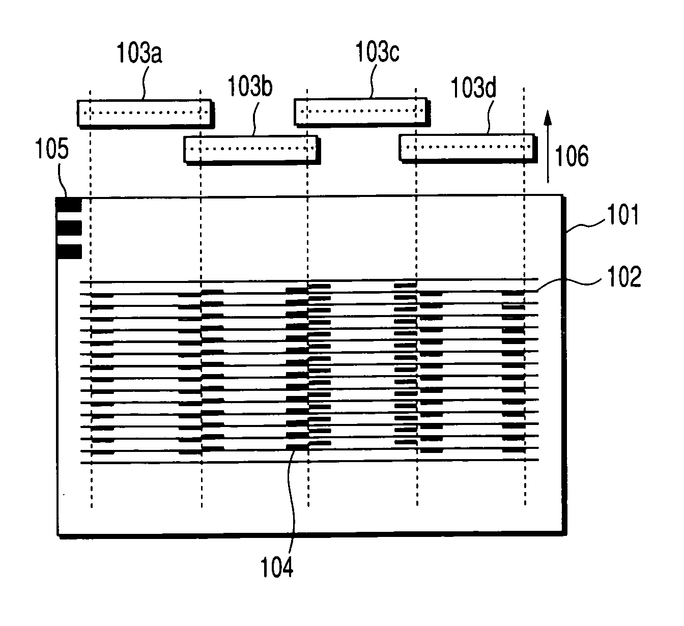
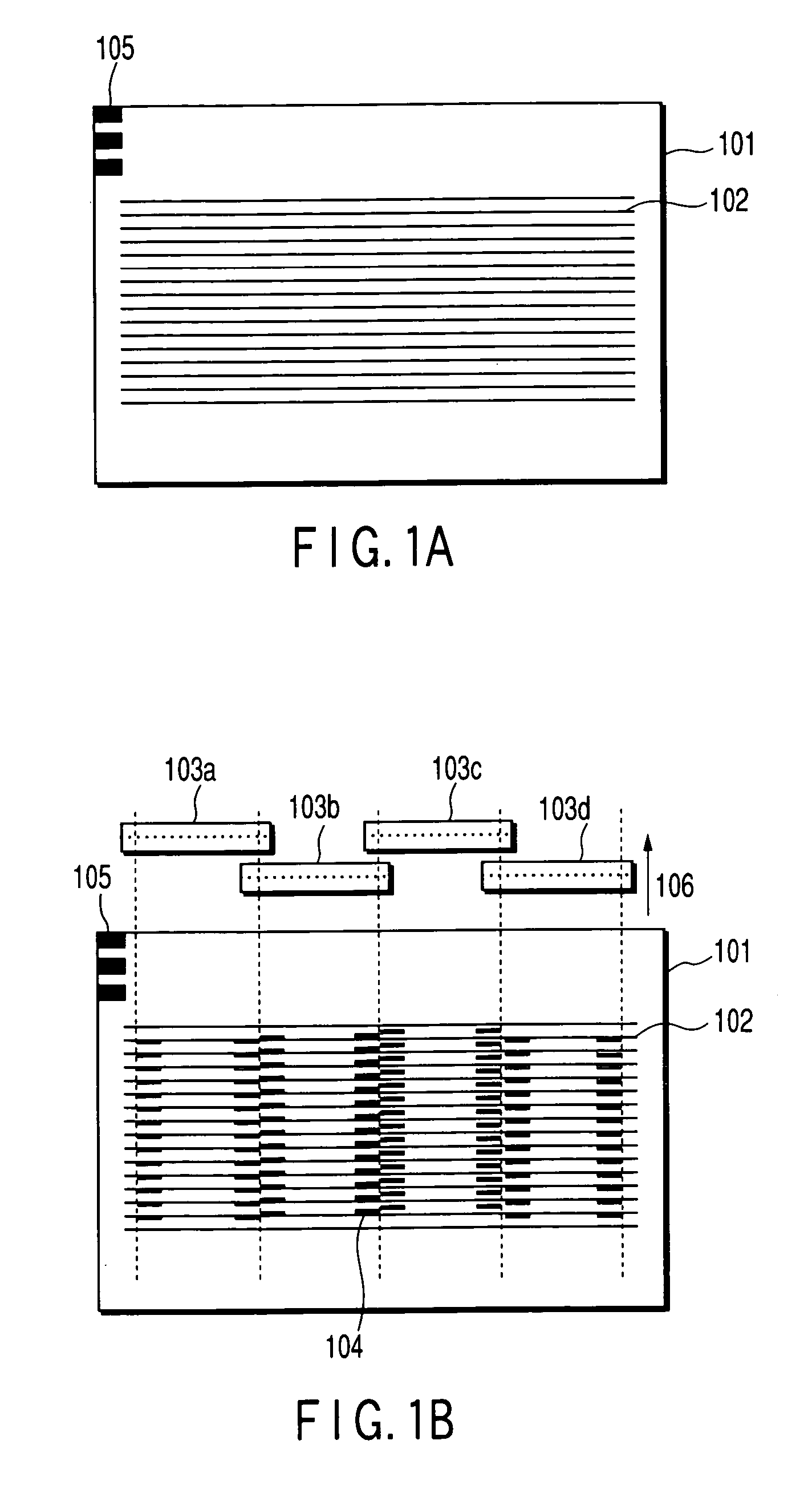
[0071]FIG. 1A is a diagram showing a first embodiment of the present invention. In FIG. 1A, reference numeral 101 denotes a recording sheet main body, 102 denotes a pattern for measurement, and 105 denotes marks indicating a type of the pattern for measurement 102. An interval between lines of the pattern for measurement 102 is twice a basic dot pitch in a sheet conveying direction of an image recording apparatus. FIG. 1B is a diagram showing a relationship between a recording head and a recorded dot. In FIG. 1B, 101, 102, and 105 are common to those of FIG. 1A.

[0072]Reference numerals 103a to 103d of FIG. 1B denote recording heads, and a positional relationship of them is shown. The recording heads 103a to 103d are arranged in such a manner that portions of recording ranges overlap with each other, and an image can be recorded in a width substantially equal to a transverse width of the recording sheet 101. The width of the pattern for measurement 102 is pref...

second embodiment

[0081](Second Embodiment)

[0082]FIG. 4 is a diagram showing a second embodiment of the present invention. In FIG. 4, 301 denotes a recording sheet main body, 302a to 302e denote patterns for measurement, and 303 denotes an image for measurement. The patterns for measurement 302a to 302e are formed beforehand on the recording sheet 301 of the present embodiment, and the image for measurement 303 is recorded by the recording head, when a correction amount of a recorded dot position is obtained. The patterns for measurement 302a to 302e have slightly different inclinations, and inclination angles are known. An interval of the patterns for measurement 302a to 302e and image for measurement 303 in the conveying direction of the recorded dot is twice the minimum dot interval in the same manner as in Embodiment 1 of the recording sheet. Reference numeral 304 denotes an identification mark for identifying a sheet type.

[0083]When the recording head is inclined and disposed with respect to the...

third embodiment

[0085](Third Embodiment)

[0086]FIG. 5 is a diagram showing a third embodiment of the present invention. In FIG. 5: 401 denotes an image memory which holds an input image; 402 denotes an image dividing section which divides the input image by a plurality of recording heads to record the images; 403 denotes an image data selection device which selects image data to be recorded from the input image and an image for measurement; 404 denotes an image memory which holds the divided image data; 405 denotes a recording head driver which drives / controls the recording head; 406 denotes a recording head; 407 denotes a ROM (generation section of the pattern for measurement) in which the data of the pattern for measurement is stored; 408 denotes an image scanner which is a pattern reading section; 409 denotes a recorded dot position calculation section; 410 denotes an image data correction section; 411 denotes a printing timing correction amount calculation section; and 412 denotes a recording sh...


PUM

PropertyMeasurementUnit
angleaaaaaaaaaa
widthaaaaaaaaaa
lengthaaaaaaaaaa

Abstract

There is disclosed a recording sheet for use in an image recording apparatus which forms an image by a recording head, the recording sheet has a pattern for measurement in which a correction amount for correction of a positional shift of a recorded dot recorded by the recording head is measurable based on a positional relationship with an image for measurement formed by the recording head, and accordingly it is possible to correct arrangement of recorded dots and to record an image without any distortion.

Description

CROSS-REFERENCE TO RELATED APPLICATIONS[0001]This is a Continuation Application of PCT Application No. PCT / JP02 / 12828, filed Dec. 6, 2002, which was not published under PCT Article 21(2) in English.[0002]This application is based upon and claims the benefit of priority from prior Japanese Patent Application No. 2001-373002, filed Dec. 6, 2001, the entire contents of which are incorporated herein by reference.BACKGROUND OF THE INVENTION[0003]1. Field of the Invention[0004]The present invention relates to image recording apparatuses such as a printer, facsimile machine, and copying machine, particularly to a recording sheet in which distortion of an image recorded by an image recording apparatus using a plurality of recording heads to increase a recording width is corrected and to image recording apparatus using this recording sheet.[0005]2. Description of the Related Art[0006]An image recording apparatus of a photosensitive recording system, thermal transfer recording system, ink jet...

Claims


Application Information

Patent Timeline
Patent Type & Authority Patents(United States)
IPC IPC(8): B41J29/393B41J2/01B41J11/42B41J29/46B41M5/00B41M5/28B41M5/30B41M5/382B41M5/50B41M5/52H04N1/047H04N1/193
CPCB41J29/393H04N1/0473H04N1/1934H04N1/193H04N2201/0471H04N2201/04717H04N2201/04734H04N2201/03162H04N2201/04787
Inventor EBIHARA, TOSHIYUKI
Owner RISO KAGAKU CORP
Learn More