
Bone collecting device

a bone collecting and bone technology, applied in the field of bone collecting devices, can solve the problems of increased self-bone problems and contamination of collected bone, and achieve the effects of improving application ability, osteoconduction, and infection control, and stably positioning

Inactive Publication Date: 2007-05-08
TAKAHASHI ATSUSHI
View PDF22 Cites 29 Cited by
  • Summary
  • Abstract
  • Description
  • Claims
  • Application Information

AI Technical Summary

Benefits of technology

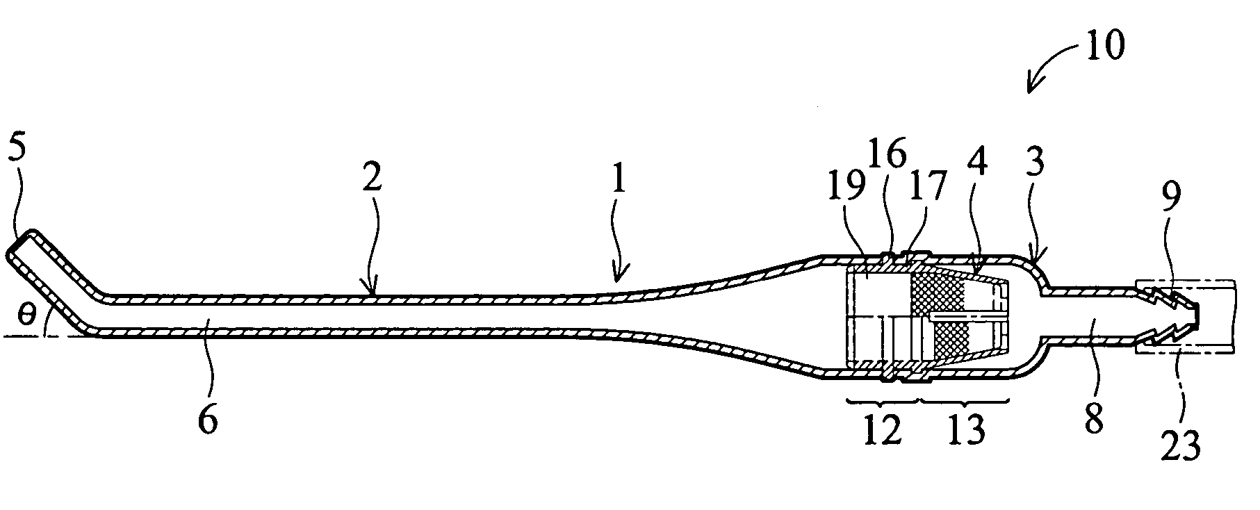
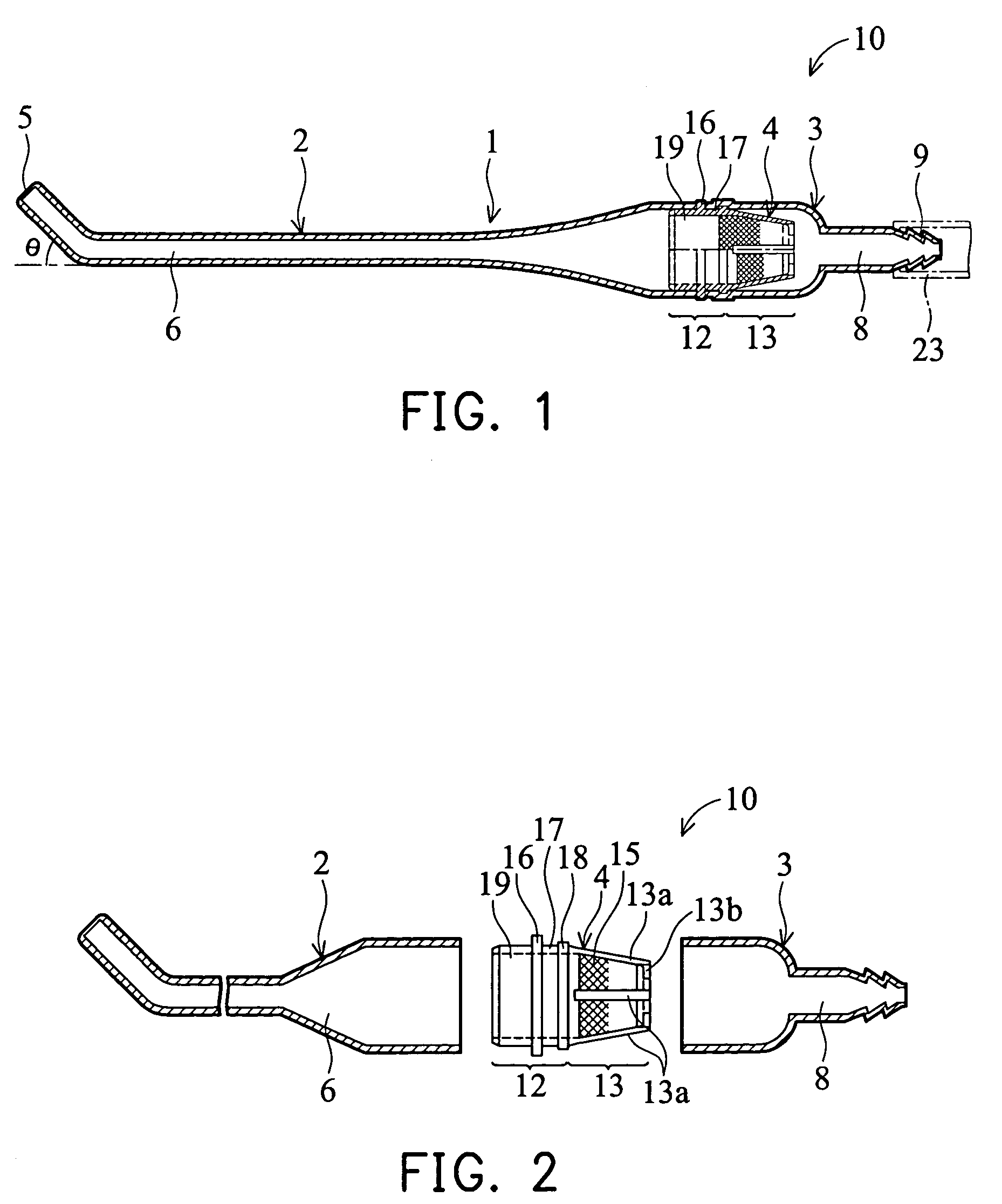
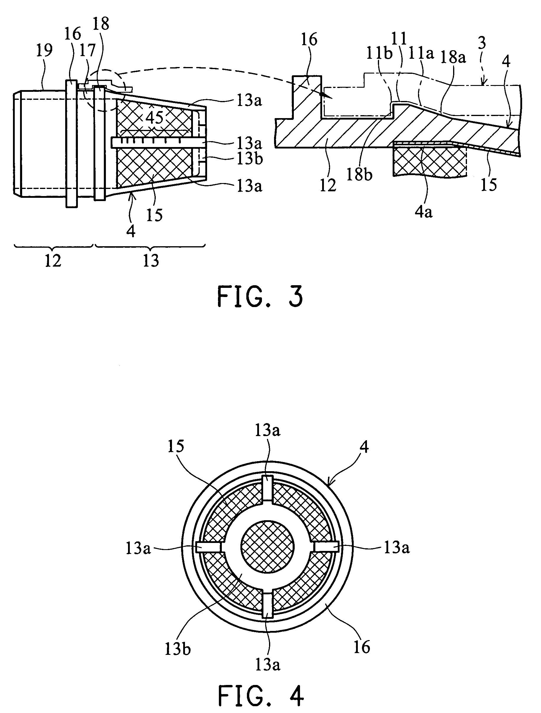
[0006]To attain the above the object, the invention provides a bone piece collecting device for filtering and collecting bone piece from an oral cavity. The device includes a suction duct, a main unit body, a filter member, and a filter holder with impermeability. The suction duct extracts liquid from the oral cavity, including at least bone piece, saliva, and blood. The main unit body includes a suctioning side part and a base end side part connected to the suctioning side part via an intermediate portion, and is coaxially connected to the suction duct. The base end side part, through which the liquid excluding the bone piece passes, is detachable from the suction duct. The suctioning side part, through which the liquid including at least the bone piece passes, is detachable from the base end side part. The filter member includes a filter part, a first joint part and a second joint part. The filter member filters the bone piece and joints the base end side part and the suctioning side part, and is detachably disposed at the intermediate portion in the main unit body. The filter part is container-shaped, and filters the bone piece from the liquid. The first joint part is fitted to an inner side of an opening of the base end side part. The second joint part is fitted to the suctioning side part and located around the first joint part, and protrudes from the opening of the base end side part. The filter holder is fitted to an outer wall of a mesh of the filter member removed from the main unit body after collecting the bone piece. The area of the bottom part of the filter holder exceeds that of the filter member such that the filter member can be stably positioned. After bone piece in the filter member press fitted to the filter holder is mixingly agitated with the other substances, it is removed. To improve application ability, osteoconduction, and infection control, when the self-bone is mixingly agitated with the other substance, the bone pieces are selectively collected by the filter assembled on the sucking chip of the dental vacuum device. When the collected bone pieces are mixingly agitated with the other substances, including liquid, held in the filter holder, its application ability can be improved and the amount of the collected bone pieces can be prevented from reducing since it needs not to be transferred to the dappen dish.
[0007]In a preferred embodiment, the device further includes an adhesive tape or a magic tape attached at the is bottom part of the filter holder. Thus, when the filter holder is fixed to an operation cuff or an operating table via the adhesive tape or magic tape, the bone filling material, including the bone pieces, can be removed without the need to manually hold the filter holder. Since the bone piece collecting device including the filter holder is prevented from tipping over or being fallen down, the precious collected bone pieces can be prevented from dispersing and that it facilitates the removal of the collected bone.
[0008]In another preferred embodiment, the filter holder is transparent or semi-transparent with a gradient on its inner wall and its outer wall such that a volume received in the filter holder can be easily weighed. Thus, it becomes possible to easily grasp in proportion the optimum amount of collected bone pieces and with the other substances mixingly agitated with the bone pieces.

Problems solved by technology

However, in clinical application, in view of easy application, osteoconduction, or infection control, the problem generated from the self-bone may increase after the collected bone is transferred to the other container and mixing agitated with the other substances.
Thus, the collected bone may be contaminated.

Method used


Image

  • Bone collecting device
  • Bone collecting device
  • Bone collecting device

Examples


Embodiment Construction

[0023]Referring to figures, an embodiment of the invention is described in the following.

[0024]FIGS. 1–12 show an embodiment of the invention. In figures, the, same reference in different figures represents the same component.

[0025]Although the basic structure of the invention is similar to conventional devices, the characteristics of the invention are shown in FIGS. 5–6. Specifically, in FIGS. 5–6, a filter member 4 for collecting bone pieces is assembled on a filter holder 20. Also, in FIGS. 7–8, a flexible bone collecting dam 30 is disposed at a front end portion 5 of a suctioning side part 2.

[0026]Next, the operation of the device shown in the above is figures is described. A main unit body 1, including the filter member 4 as shown in FIG. 1, is disposed at a front end of a vacuum device, and collects bone pieces to be transplanted. After sufficient amount of bone pieces is collected, the main unit body 1 can be disassembled so as to remove the filter member 4. The outer surface...


PUM

PropertyMeasurementUnit
Transparencyaaaaaaaaaa

Abstract

A bone piece collecting device, wherein, when bone pieces are mixing agitated with the other substances while preventing the loss of the cut bone pieces collected on a filter and contamination thereof by saliva by a self-bone transplanting method, a filter part is installed in a filter holder with impermeability to eliminate the operation for transferring the bone pieces to the other container, a collected bone container for filling bones is prevented from being fallen down by stably fixing the container to a cuff for operation or an operation table with an adhesive tape or a magic tape installed at the bottom part of the filter holder so as to facilitate the removal of the collected bones, and a gradient is marked on the transparent or semi-transparent material of the filter holder so that the amount of collected bones can be weighed easily.

Description

BACKGROUND OF THE INVENTION[0001]1. Field of the Invention[0002]The invention relates to a technology for collecting bone pieces when an implant socket is drilled during a dental implant operation or a technology for selectively collecting a bone from a non-transplant site by a bone piece collecting device and filling collected bone pieces to a transplant site.[0003]2. Description of the Related Art[0004]In a conventional implant operation, a self-bone transplanting method is often applied when the amount of the bone is insufficient to be transplanted into a transplant site. When an implanted socket is drilled in a jawbone, cut bone pieces from the jawbone, and blood, saliva, cooling water from a turbine are filtered and selectively collected by a sucking chip of a dental vacuum device via a filter. The collected bone piece itself can be directly transplanted by a syringe-shaped bone piece collecting device. Alternatively, the collected bone piece can be transplanted after it is tra...

Claims


Application Information

Patent Timeline
IPC IPC(8): A61C17/14A61B10/00A61B10/02A61B19/00A61C8/00A61C17/06A61F2/46A61M1/00B01D35/02
CPCA61C8/0089A61C17/043A61C17/046A61F2/4644A61M1/0056A61B10/025B01D35/02B01D2201/02B01D2201/4084A61C17/08A61C17/065A61M1/79
Inventor TAKAHASHI, ATSUSHI
Owner TAKAHASHI ATSUSHI
Learn More