Touch panel input device

a technology of input device and touch panel, which is applied in the direction of mechanical pattern conversion, instruments, computing, etc., can solve the problems of limited design of the exterior of the device, high cost of parts, and difficulty in knowing whether or not an input operation is completed

Inactive Publication Date: 2007-05-08
SMK CORP
View PDF9 Cites 228 Cited by
  • Summary
  • Abstract
  • Description
  • Claims
  • Application Information

AI Technical Summary

Benefits of technology

[0032]Because a single layer substrate made of a piezoelectric material can constitute the piezoelectric substrate, the thickness of the piezoelectric substrate can be made thin, and can be interposed in a slight gap between the movable plate and the support substrate.
[0033]Because a space for placing the spacer mem

Problems solved by technology

An operator who presses the movable plate has difficulty knowing whether or not an input operation is completed.
The design of the exterior of the device is also restricted.
Because the manufacturing process for laminating multiple piezoelectric substrates comprises multiple processes including attaching a pair of drive electrodes to the individual layers, and then laminating the piezoelectric substrates to which the drive electrodes are attached in the thickness direction for

Method used


Image

  • Touch panel input device
  • Touch panel input device
  • Touch panel input device

Examples


Embodiment Construction

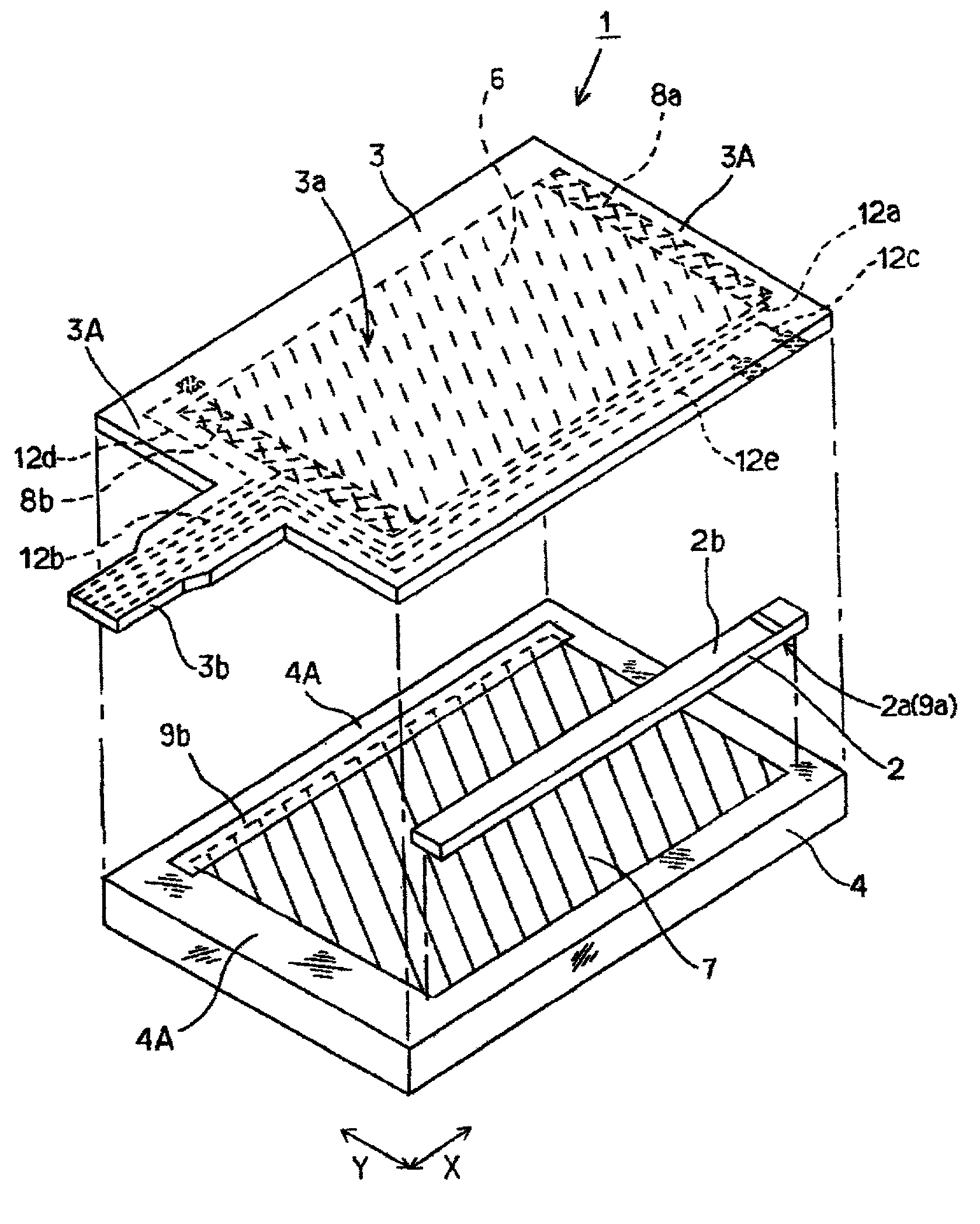
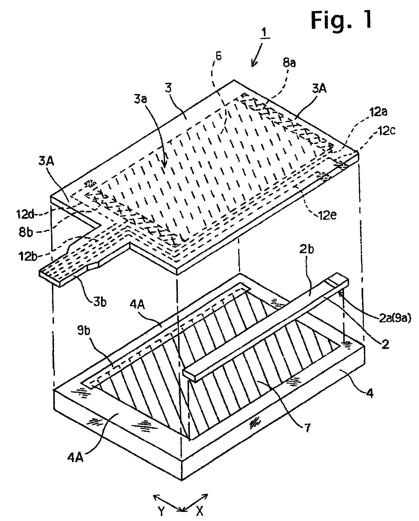
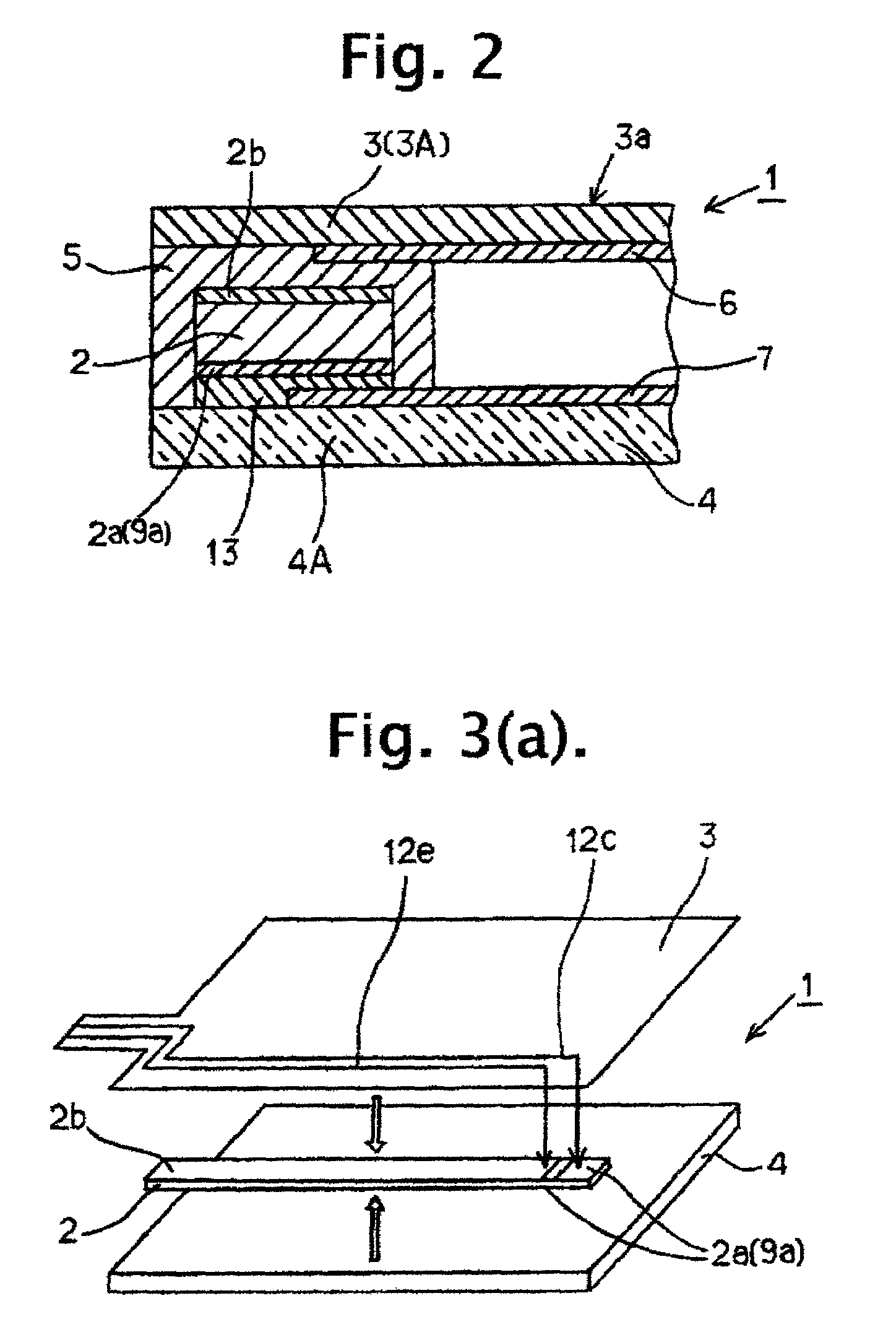
[0058]Referring first to FIGS. 1 and 2, a touch panel input device 1 according to the present embodiment adopts a so-called resistance-sensitive tablet system where uniform resistor films form conductive layers on facing surfaces. Voltages generated upon touching the external surface are processed to detects a contact position (a pressed position) between the conductive layers.

[0059]A movable plate 3 is a flexible rectangular sheet of a suitable transparent plastic material such as, for example, PET (polyethylene terephthalate). Although an arbitrary material which slightly bends toward a support substrate 4 described below is used as a material for the movable plate 3, when a transparent material is used for showing a display part (not shown) provided inside the support substrate 4 as the present embodiment, the material therefor could include a glass substrate, an acrylic board for providing a certain degree of stiffness, and a polycarbonate (PC), a polyethersulfone (PES), and a p...


PUM


Abstract

A piezoelectric substrate is fixed to the movable plate or the support substrate directly or through a drive electrode of the piezoelectric substrate. When a pressure on an input operation surface is detected, a drive voltage is impressed on the drive electrodes of the piezoelectric substrate. In response, the piezoelectric substrate vibrates the movable plate or the support substrate, thereby providing tactile feedback to an operator. Because the movable plate or the support substrate directly vibrates without an independent vibrating source, there is no energy loss or transmission delay caused by transmitting the vibration, and finely control of the contraction and expansion of the piezoelectric substrate allows fine control of the vibration. In one embodiment, the drive voltage is modulated with signals dependent on the location of the pressure. In another embodiment, the drive voltage is modulated with audio frequencies to create a speaker.

Description

BACKGROUND OF THE INVENTION[0001]1. Field of the Invention[0002]The present invention relates to a touch panel input device for vibrating a movable plate which is pressed, or a support substrate for supporting the movable plate, and generating an input operation feeling for an operator when the operator presses the movable plate. More specifically, the present invention relates to a touch panel input device for using a piezoelectric substrate to vibrate the movable plate or the support substrate.[0003]2. Description of the Related Art[0004]A touch panel input device includes a movable plate and a support substrate which are laminated with a slight gap between them to separate conductor layers on the opposing surfaces of the movable plate and the support substrate. The input device electrically detects a contact between the conductor layers at a pressed position when the movable plate is pressed, and provides information to a processing device such as a personal computer about the pr...

Claims


Application Information

Patent Timeline
IPC IPC(8): G09G5/00G06K11/06G06F3/045G06F3/00G06F3/01G06F3/041H01L41/09
CPCG06F3/016G06F3/0414
Inventor YOSHIKAWA, OSAMUISHIBASHI, HIROTOSHI
Owner SMK CORP
Why Eureka
Try Eureka