Measurement method by OTDR and terminal station apparatus

a technology of terminal station and measurement method, which is applied in the direction of multiplex communication, transmission monitoring, instruments, etc., can solve the problems of limited measurement distance from a terminal station with an otdr, and limited transmission distance of otdr signal light, so as to improve increase the dynamic range, and enhance the effect of raman amplification

Active Publication Date: 2007-05-08
FUJITSU LTD +1
View PDF17 Cites 69 Cited by
  • Summary
  • Abstract
  • Description
  • Claims
  • Application Information

AI Technical Summary

Benefits of technology

[0015]According to the present invention, the main signal light can be used as pump light of OTDR signal light. Therefore, the OTDR signal light is Raman amplified so that the dynamic range is increased and a long span optical transmission line can be surveyed without newly providing any pump light source for the OTDR signal light.
[0016]In the method, the OTDR signal light may be Raman amplified by using the main signal light that is transmitted from the first terminal station, or by using the main signal light transmitted from the second terminal station. In addition, the OTDR signal light can be Raman amplified by using bidirectional main signal light as bidirectional pump light. Accordingly, the effect of Raman amplification can be enhanced.

Problems solved by technology

However, transmission distance is limited even though Raman amplification is performed since no relay is provided.
Therefore, transmission distance of OTDR signal light is limited so that measurement distance from a terminal station that has an OTDR is limited.
However, from the viewpoint of measurement by OTDR, since absorption loss by EDF is large at 1550 nm band that is generally used as OTDR signal light, it is difficult to measure loss distribution beyond EDF from a terminal station that performs OTDR measurement.
In addition, even when light of 1650 nm band that can pass through the EDF is used, good S / N ratio cannot be obtained since transmission loss by optical fiber is large at the 1650 nm band.
Therefore, it is difficult to measure loss distribution along a long distance length of optical fiber by the no-relay transmission system.
As mentioned above, as to the no-relay transmission system, there is a problem in that OTDR measurement of loss distribution cannot be performed for a long span optical transmission line.

Method used


Image

  • Measurement method by OTDR and terminal station apparatus
  • Measurement method by OTDR and terminal station apparatus
  • Measurement method by OTDR and terminal station apparatus

Examples


first embodiment

(First Embodiment)

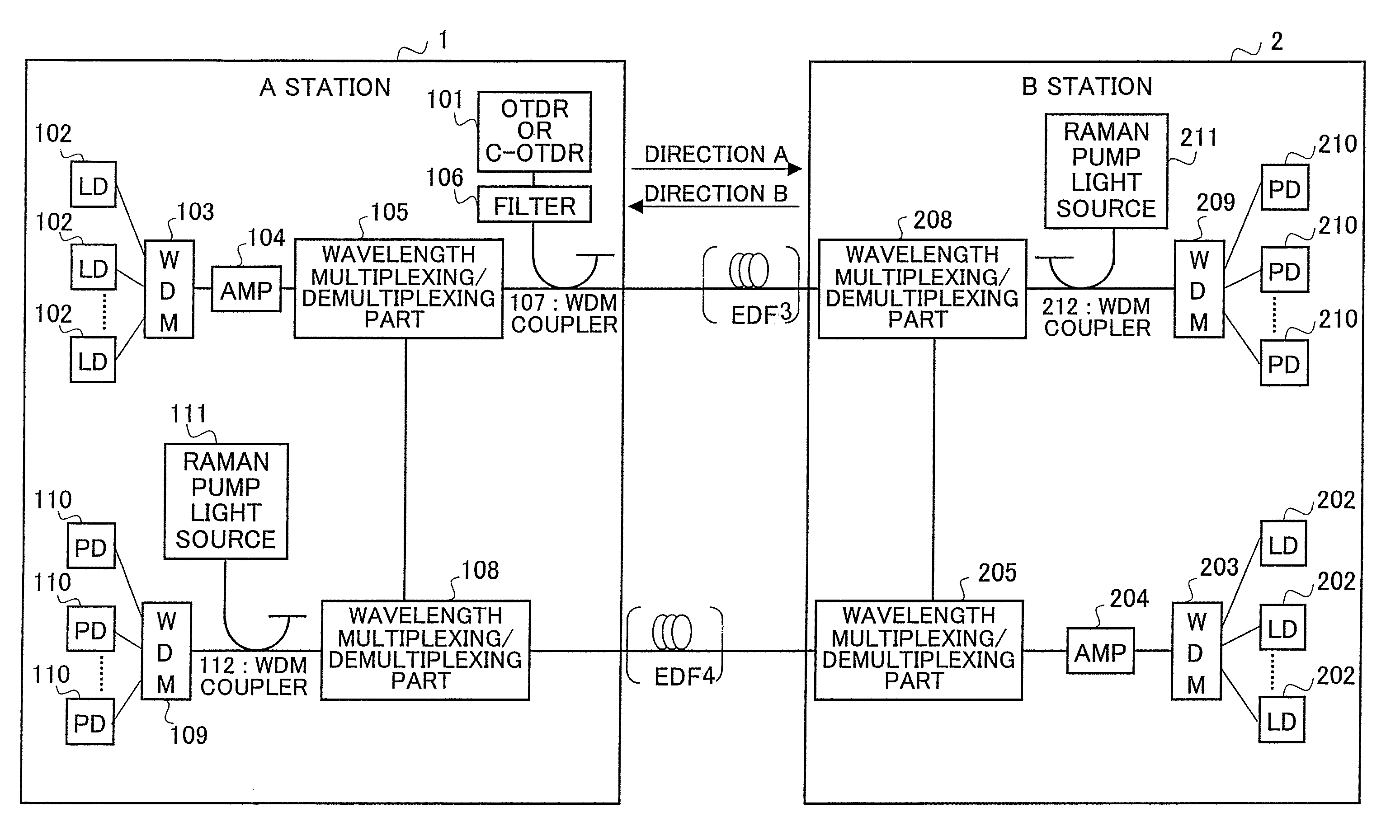
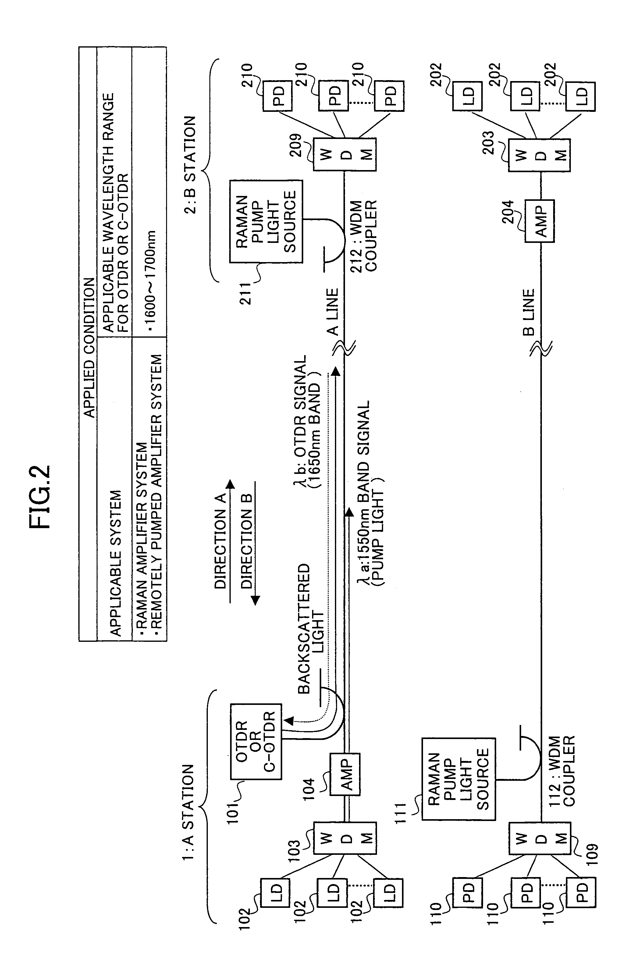
[0052]FIG. 2 is a figure for explaining the OTDR measurement method according to the first embodiment of the present invention. As shown in FIG. 2, the wavelength multiplexing / demultiplexing parts 105 and 108 are not provided in this embodiment.

[0053]According to the first embodiment shown in FIG. 2, light of 1650 nm band (λb) is used as the OTDR signal light. The wavelength range of the OTDR signal light in this embodiment is 1600–1700 nm. In this embodiment, C-band main signal light (λa: 1550 nm band) emitted from the A station 1 is used as pump light to Raman amplify OTDR signal light (λb: 1650 nm band) emitted from the OTDR 101, so that the dynamic range is increased. That is, as shown in FIG. 3, since the light of 1650 nm band can be Raman amplified by the light of 1550 nm band, the light emitted from the main signal light source can be used as the Raman pump light for OTDR signal light. The example in which 1550 nm band light is Raman amplified by 1450 nm ban...

second embodiment

(Second Embodiment)

[0055]FIG. 4 is a figure for explaining an OTDR measurement method according to the second embodiment of the present invention.

[0056]In the second embodiment, light of 1550 nm band (λa) that is the same as the main signal light is used as the OTDR signal light. The OTDR signal light is Raman amplified by using pump light (λc: 1450 nm band) emitted from the Raman pump light source 111 that is usually used for Raman amplifying signal light transmitted in the B direction, so that the distance of OTDR measurement is increased. The wavelength range of the OTDR signal light in this embodiment is 1500–1600 nm.

[0057]In this embodiment, the wavelength multiplexing / demultiplexing parts 105 and 108 function as optical switches 12 and 13 respectively. When OTDR measurement is not performed, the optical switch 12 transmits the main signal light emitted from the AMP 104 over the A line. When OTDR measurement is not performed, the optical switch 12 cuts off the main signal light...

third embodiment

(Third Embodiment)

[0060]FIG. 5 is a figure for explaining an OTDR measurement method according to the third embodiment of the present invention.

[0061]In the third embodiment, light of 1650 nm band (λb) is used as the OTDR signal light. The wavelength range of the OTDR signal light in this embodiment is 1600–1700 nm. The OTDR signal light (λb: 1650 nm band) from the OTDR 101 is Raman amplified by using the main signal light (λa: 1550 nm band) from the A station light source. Further, the main signal light (λa: 1550 nm band) used for amplifying the OTDR signal light is Raman amplified by using pump light (λc: 1450 nm band) emitted from the Raman pump light source 111. That is, λa is pumped by using first-order Stokes wave of λc, so that λb is pumped by using the original power of λa as first-order Stokes wave and using the power of λa pumped by λc as second-order Stokes wave. Accordingly, the OTDR signal light is amplified so that dynamic range is enlarged and the distance of OTDR mea...


PUM

PropertyMeasurementUnit
wavelength bandaaaaaaaaaa

Abstract

In a method for performing OTDR measurement in an optical transmission system including a first terminal station and a second terminal station, OTDR signal light is transmitted from an OTDR provided in the first terminal station to the second terminal station, in which the OTDR signal light is Raman amplified by using main signal light of the optical transmission system as pump light.

Description

CROSS-REFERENCE TO RELATED APPLICATION[0001]This patent application is based on Japanese Priority Patent Application No. 2003-070318, filed on Mar. 14, 2003, the entire contents of which are hereby incorporated by reference.BACKGROUND OF THE INVENTION[0002]1. Field of the Invention[0003]The present invention relates to a technique for measuring loss distribution along a length of optical fiber in an optical transmission system by using an OTDR (optical time domain reflectometer).[0004]2. Description of the Related Art[0005]The OTDR is used for detecting distance distribution of transmission loss in optical fiber or for locating fiber fault or the like. By using the OTDR, a pulse of light is transmitted down the fiber and the backscattered signal is detected. The intensity of the backscattered light provides a measure of the loss in the optical fiber, and the time between transmitting the pulse and obtaining the backscattered light provides a measure of distance in the optical fiber....

Claims


Application Information

Patent Timeline
Patent Type & Authority Patents(United States)
IPC IPC(8): G01N21/00G01M11/02H04B10/00H04B10/07H04B10/071H04B10/077H04B17/00H04J14/00H04J14/02
CPCH04B10/071H04B10/2916
Inventor MAEHARA, TAKAYUKIHARASAWA, SHINICHIROUFUNATSU, GENTAROMAEDA, HIDEKINAKA, AKIRA
Owner FUJITSU LTD
Why Eureka
Try Eureka