Multi-layer record carrier and method of manufacturing thereof and recording thereon, with reduced transmission differences in the upper layer

a record carrier and multi-layer technology, applied in the field of multi-layer record carriers, can solve the problems of significant increase in the transmission area, read the lower layer, and increase the problem of the header area, so as to reduce the transmission differences in the upper information or recording layers, increasing the complexity of the system

Inactive Publication Date: 2007-05-08
KONINKLIJKE PHILIPS ELECTRONICS NV
View PDF16 Cites 7 Cited by
  • Summary
  • Abstract
  • Description
  • Claims
  • Application Information

AI Technical Summary

Benefits of technology

[0016]It is an object of the present invention to provide a multi-layer record carrier, a method and apparatus for recording on such a multi-layer record carrier, and a method of manufacturing such a multiple layer record carrier, by means of which transmission differences in the upper information or recording layers can be reduced without significantly increasing the complexity of the system.
[0021]Accordingly, by setting the length of the first and second guard fields such that the end position of the second guard field of a preceding data block is located within the area of the first guard field of the succeeding data block, the gap portion between neighboring data clusters or data blocks is prevented. Thereby, a uniform transmissivity can be achieved in the upper layers, since no gaps are provided in the linking areas.
[0024]Preferably, the length of a gap portion provided between the second guard field and the header area or between the header area and the first guard field is greater or equal than the predetermined minimum length of the first and second guard fields. In particular, the length of the gap portions may be equal to the length of the first and second guard fields. Thereby, the length of the gap in the upper layer is chosen such that the phase change data in the upper layer is not “seen” anymore by the reading beam when reading the header area in the deepest layer. By using, in the at least two information layers, the same length for the gap and guard fields, symmetry between the information layers can be achieved.

Problems solved by technology

In dual or multi-layer systems, the above linking method leads to the problem that the lower layer is read while a significant area of the laser beam passes through the gaps of the upper layer or layers.
This problem increases when the gaps are large, such as, for example, in DVR systems where the gaps may have a length of typically about 150 μm while the diameter of the beam in the upper layer is about 40 μm when reading the lower layer and when the gaps are at the same angular position in neighboring tracks, such as, for example, on the radial areas of a CLV or ZCAV system where an integer number of ECC blocks fits almost exactly on an integer multiple of one or several circumferences.
Secondly, just before and just after the header area, the groove is not yet written with phase change data due to the fact that in a DVR system, the segment run-in starts and the segment run-out ends with a gap before the data is actually written.
Thus, the transmission problem due to the gap portion in the upper layer occurs between data clusters and between a data cluster and a header area.
The transmission problem due to the header area is significantly increased in case of a (random) misalignment between the header spokes of the upper and of the lower information layers.

Method used


Image

  • Multi-layer record carrier and method of manufacturing thereof and recording thereon, with reduced transmission differences in the upper layer
  • Multi-layer record carrier and method of manufacturing thereof and recording thereon, with reduced transmission differences in the upper layer
  • Multi-layer record carrier and method of manufacturing thereof and recording thereon, with reduced transmission differences in the upper layer

Examples


Embodiment Construction

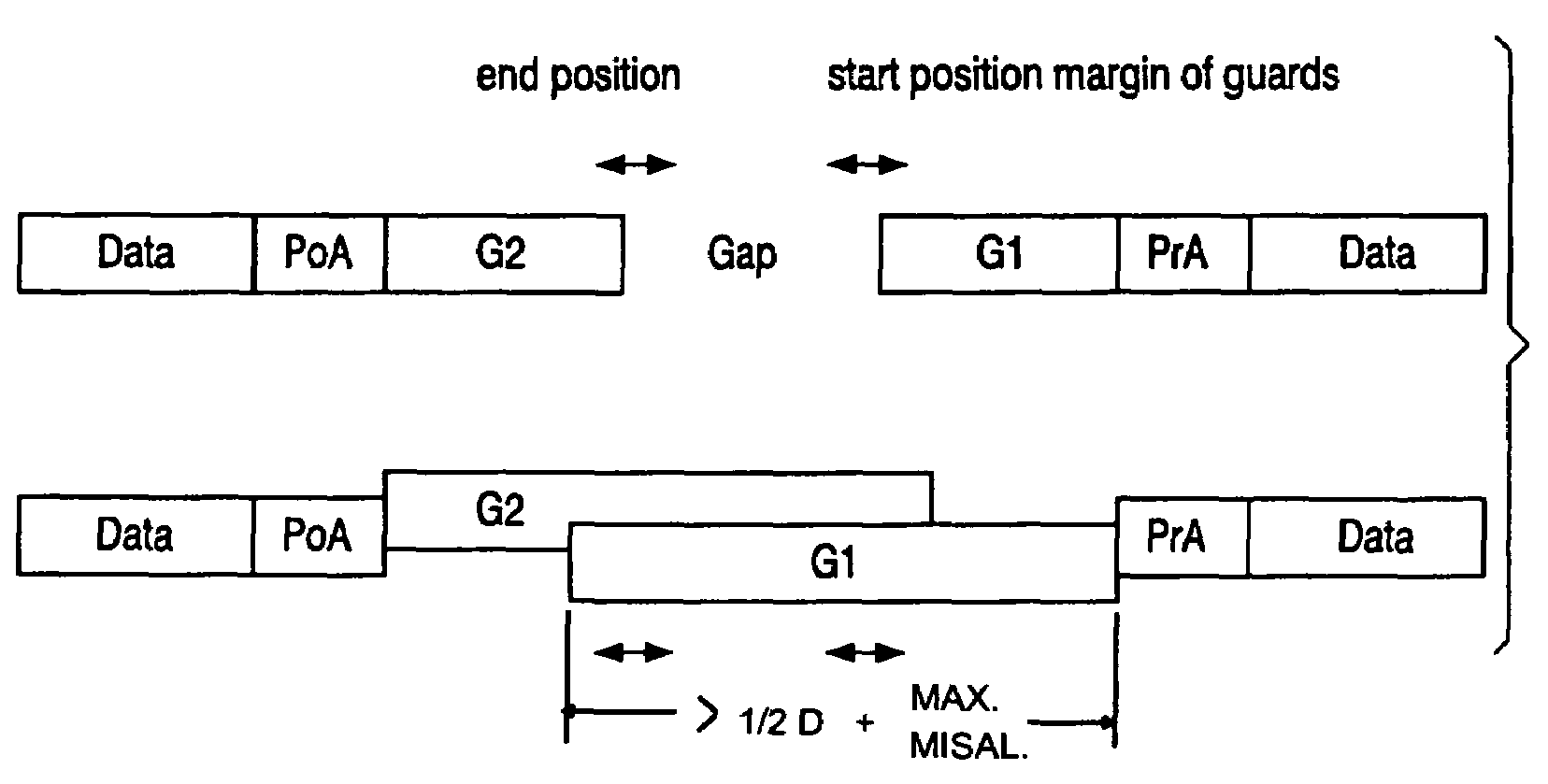
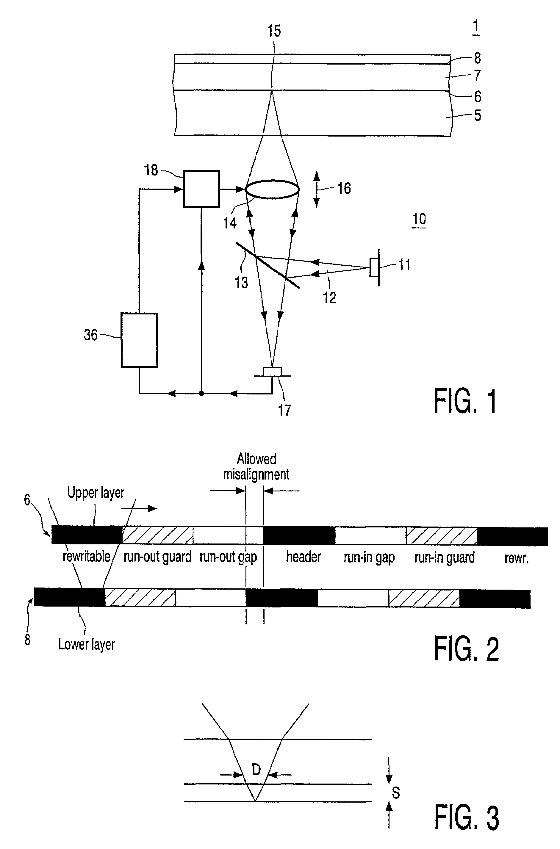
[0036]The preferred embodiment will now be described on the basis of an optical disk player for recording on and reproducing from a dual layer optical disk.

[0037]FIG. 1 shows a cross-section of the dual layer record carrier 1 and a scanning head of a scanning device 10 for optically scanning the information stored in the record carrier 1. The record carrier 1 has a transparent substrate 5 provided with a first information layer 6 and a second information layer 8 substantially parallel thereto, separated by a transparent spacer layer 7. Although only two information layers are shown in this embodiment of the record carrier 1, the number of information layers may be more than two.

[0038]The scanning device 10 comprises a radiation source 11, for example, a diode laser which generates a radiation beam 12, such as a laser beam. The radiation beam is formed to a focusing spot 15 via a beam splitter 13, for example, a semitransparent plate, and a lens system 14, for example, an objective l...


PUM

PropertyMeasurementUnit
diameteraaaaaaaaaa
diameteraaaaaaaaaa
displacementaaaaaaaaaa

Abstract

A multi-layer record carrier and method of manufacturing thereof and recording thereon, includes data written in units of blocks on tracks of at least two information layers. A first guard field is written at the start of a data block and a second guard field is written at the end of the data block. The power in the focused spot in the deepest of the at least two information layers is maintained substantially at an optimal value, by setting the length of the first and second guard fields such that the end position of the second guard field of a preceding data block is located within the area of the first guard field of the succeeding data block. Thereby, gap portions between the first and second guard fields can be prevented. Alternatively, the length of the first and second guard fields is set to be approximately equal to the sum of half the diameter of a recording beam in the upper one of the at least two information layers when focused on the lowest one of the at least two information layers and a maximum allowed misalignment between the two layers. Thereby, the area through which the beam passes in the information layer is of a uniform nature, when user data is being read or written. The at least two information layers are aligned by optically measuring and aligning alignment marks, such as header spokes, at predetermined measuring points.

Description

BACKGROUND OF THE INVENTION[0001]1. Field of the Invention[0002]The present invention relates to a multi-layer record carrier, such as, a recordable optical disk of the write-once or rewritable type, suitable to be scanned by a single scanning device and provided with at least two substantially parallel information layers, wherein data is written in units of blocks on tracks of the at least two information layers. Furthermore, the present invention relates to a method and a recording apparatus for recording data on such a record carrier, and a method of manufacturing such a record carrier.[0003]2. Description of the Related Art[0004]Optical data storage systems, such as optical disk drives, allow a storage of large quantities of data on an optical medium. The data is accessed by focusing a laser beam onto the recording layer of the medium and then detecting the reflected light beam. In reversible or rewritable phase-change systems, optical media with two stable phases is used. A dat...

Claims


Application Information

Patent Timeline
Patent Type & Authority Patents(United States)
IPC IPC(8): G11B7/00G11B7/0045G11B7/007G11B7/24038G11B7/26G11B20/12
CPCG11B7/0045G11B7/006G11B7/00745G11B7/24038G11B7/26G11B2020/1277
Inventor VAN WOUDENBERG, ROEL
Owner KONINKLIJKE PHILIPS ELECTRONICS NV
Why Eureka
Try Eureka