Power generating system utilizing buoyancy

a technology of power generation system and buoyancy, which is applied in the direction of reciprocating piston engines, positive displacement engines, working fluids for engines, etc., can solve the problems that the related art generating sets have not been able to meet the demand for electric power sufficiently, and achieve the effect of low engagement resistance and smooth turning

Inactive Publication Date: 2007-05-15
TAKEUCHI SEISAKUSHOKK
View PDF7 Cites 46 Cited by
  • Summary
  • Abstract
  • Description
  • Claims
  • Application Information

AI Technical Summary

Benefits of technology

[0008]The structure of this gas supply means as compared with a gas supply means for sending the gas left in the form of large-diameter bubbles, which are supplied into the interior of the pipe, into the liquid in the interior of the tower is capable of sending smoothly with a low resistance the gas in the form of a plurality of bubbles of a very small diameter from the plural holes of a very small diameter. The plural bubbles of a very small diameter of the gas sent out from the holes of a very small diameter of the circumferential wall of the pipe into the liquid in the interior of the tower are collected reliably without omission in an inner side of the gas introduction nozzle. The resultant bubbles can be sent accurately in the form of bubbles of a large diameter, etc. from the front end of the gas introduction nozzle into the bucket positioned on the lower portion of the side of the conveyor turned in the interior of the tower in the upward direction.
[0019]In such a case, the conveyor formed by a combination of a chain and sprockets can be turned in the liquid in the interior of the tower accurately in the vertical direction without causing the conveyor to slip. In accordance with the turning of the chain, rotary shafts of the sprockets supporting the chain can be turned reliably in the direction in which the chain is turned. The generator connected to the rotary shaft can be turned reliably in the chain turning direction. During this time, the chain can be turned smoothly with a low engagement resistance around the sprockets by using as a lubricant the liquid stored in the interior of the tower.

Problems solved by technology

However, as a matter of regret, any of these related art generating sets has not come to satisfy a demand for electric power sufficiently in a modern society in which a large quantity of electric power is consumed.

Method used


Image

  • Power generating system utilizing buoyancy
  • Power generating system utilizing buoyancy
  • Power generating system utilizing buoyancy

Examples


Embodiment Construction

[0023]The best mode for carrying out the invention will now be described with reference to the drawings.

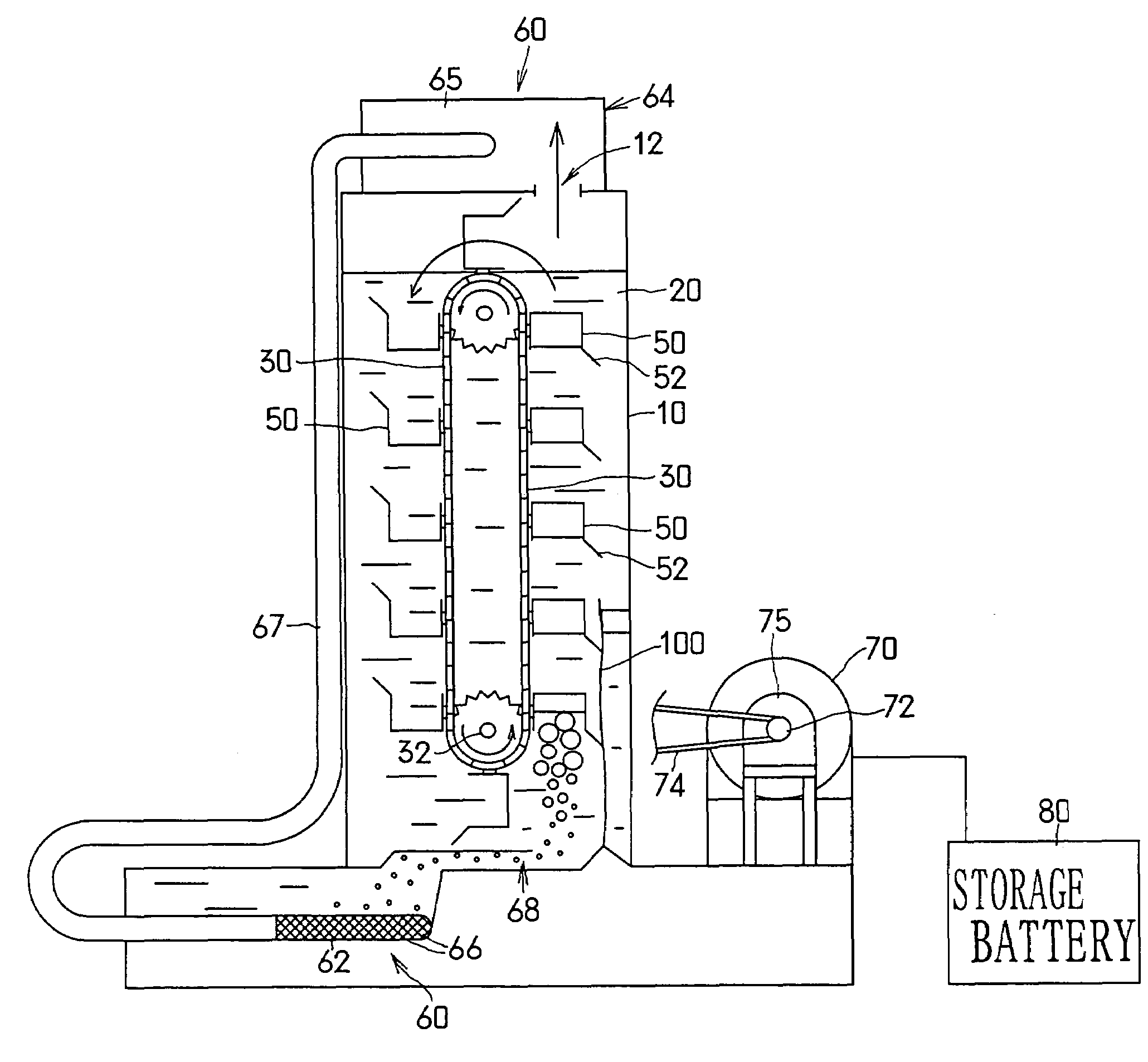
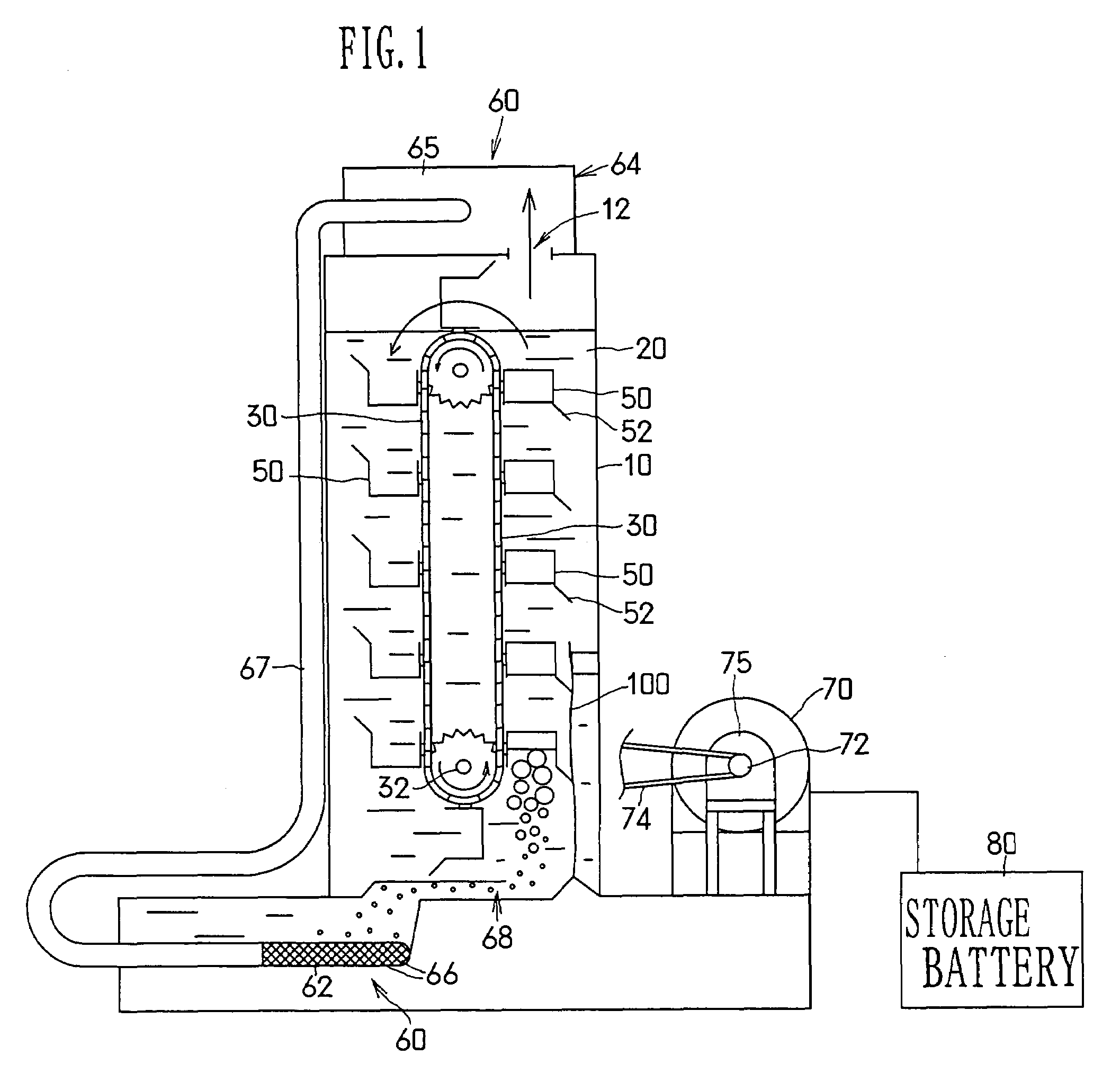
[0024]FIG. 1 to FIG. 3 show a preferred embodiment of the generating set according to the invention.

[0025]This generating set is provided with a vertically standing cylindrical tower 10 in which a liquid 20 is stored. The tower 10 is provided at an upper end thereof with a gas discharge hole 12 adapted to let a gas rising in a liquid 20 in the interior of the tower 10 and reaching the upper end of the interior of the tower 10 escape therefrom to the outside thereof. In the interior of the tower, a conveyor 30 extending vertically, immersed in the liquid 20 and having the shape of a loop is rotatably provided. Along longitudinal outer sides of the conveyor 30, a plurality of buckets 50 are arranged at predetermined intervals and fixed thereto. The buckets 50 have the shape of a cubic box opened widely at upper ends thereof, and arranged plurally along the outer side of the conveyor...


PUM


Abstract

A generating set formed so that a generator 70 connected to a rotary shaft 32 turning and supporting a conveyor 30 by utilizing the power by which a gas supplied by a supply means 60 into a bucket 50 positioned on a lower portion of the side of the conveyor 30 which is turned upward in the interior of a tower 10 is moved up with the bucket 50 in a liquid 20 stored in the interior of the tower 10 as the gas receives the buoyancy of the liquid. In this generating set, the supply means 60 is formed so as to turn compressed air into a plurality of bubbles of a very small diameter, send out these bubbles into the liquid 20 in the interior of the tower, and hold down to a low level the resistance occurring when the compressed air is sent out into the liquid 20 in the interior of the tower. An electric power energy value obtained from the generator 70 is increased with respect to a value of the energy consumed by the supply means 60.

Description

TECHNICAL FIELD[0001]This invention relates to a buoyancy-utilizing generating set adapted to rotate a generator by utilizing the buoyancy of a bubbled gas moving up in a liquid.BACKGROUND ART[0002]Various methods of obtaining electric power from a clean energy source harmless to the earth environment have been attempted. These methods include methods of developing, for example, a generating set utilizing wind power, a generating set utilizing wave power, and a generating set utilizing solar energy, and the like.[0003]However, as a matter of regret, any of these related art generating sets has not come to satisfy a demand for electric power sufficiently in a modern society in which a large quantity of electric power is consumed.[0004]The present invention has been made in view of such problems, and aims at providing a generating set adapted to rotate a generator by utilizing buoyancy occurring in a gas sent in the form of bubbles into a liquid, such as water, and capable of greatly ...

Claims


Application Information

Patent Timeline
Patent Type & Authority Patents(United States)
IPC IPC(8): F03C1/00F03B9/00F03B17/02F03B17/04
CPCF03B17/02F03B17/04F05B2210/401Y02E10/20
Inventor TAKEUCHI, AKIO
Owner TAKEUCHI SEISAKUSHOKK
Why Eureka
Try Eureka