Adjusting airflow in turbine component by depositing overlay metallic coating

a technology of metallic coating and airflow, which is applied in the direction of machines/engines, mechanical equipment, light and heating equipment, etc., can solve the problems of enlarg obstructing affecting the airflow of the liners,

Active Publication Date: 2007-05-15
GENERAL ELECTRIC CO
View PDF34 Cites 37 Cited by
  • Summary
  • Abstract
  • Description
  • Claims
  • Application Information

AI Technical Summary

Benefits of technology

[0010]The method and turbine component of this invention provides a number of benefits and advantages. These include but are not limited to: (1) providing the ability to repair or correct the airflow in turbine components, such as combustor liners, having a plurality of airflow holes so as to come within desired airflow specification or limits; (2) providing the ability to locally correct or change the airflow within specific regions or areas having such airflow holes as needed or desired, including controlling such airflow within desired specifications or limits; (3) recovering and repairing previously used or operational combustor liners and other turbine components having a plurality of airflow holes in a cost effective and efficient manner; (4) performing such recovery or repair of the turbine component without having to remove original or restored thermal barrier coatings or otherwise undesirably altering the physical or chemical properties, or physical dimensions of the component; and (5) recovering or salvaging turbine components manufactured with airflow greater than desired operational specifications or limits.

Problems solved by technology

Repair of the combustor liners, and in particular repair of the cracks that typically form in the liners during operation and use, can cause at least some of the very small “nugget” and “transpiration” holes to become obstructed, occluded, plugged, or otherwise blocked which can then require chemical and / or mechanical processes to reopen the holes.
The reopening of these airflow holes, as well as the chemical stripping process that removes the coatings and contaminants, can also remove some of metal substrate of the combustor liner where these holes are located, resulting in enlarging of these holes.
These enlarged airflow holes can significantly and undesirably increase the airflow of these liners.
Indeed, after several cycles of such cleaning and repair, the airflow can be increased to the extent that the combustor liner is no longer usable.
Problems in controlling airflow can also occur during the original manufacture of the combustor liners.
While a certain amount of control can be exercised over the pattern and size of the drilled holes, it is still extremely difficult to provide combustor liners that have a consistent pattern and size of holes such that the airflow rate is within desired limits.
While this method provides the ability to adjust the airflow through the airflow holes, the physical vapor deposition apparatus, because of its size, may not provide the flexibility needed to use it with some turbine components.
In addition, thermal barrier coatings typically comprise ceramic materials that may or may not adhere adequately to the metal surface of the liner over time without an overlay metallic bond coat layer.

Method used


Image

  • Adjusting airflow in turbine component by depositing overlay metallic coating
  • Adjusting airflow in turbine component by depositing overlay metallic coating
  • Adjusting airflow in turbine component by depositing overlay metallic coating

Examples


Embodiment Construction

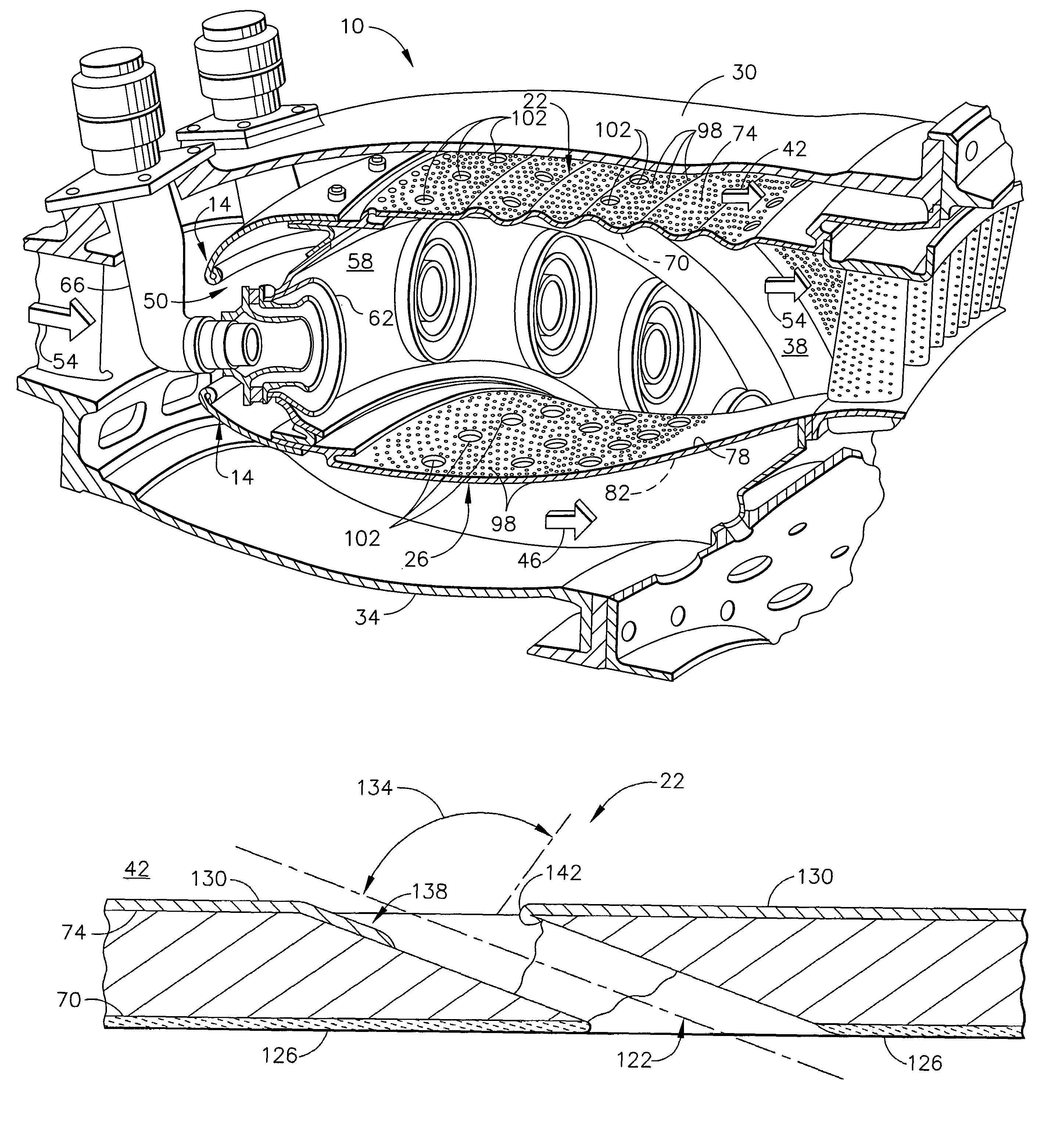
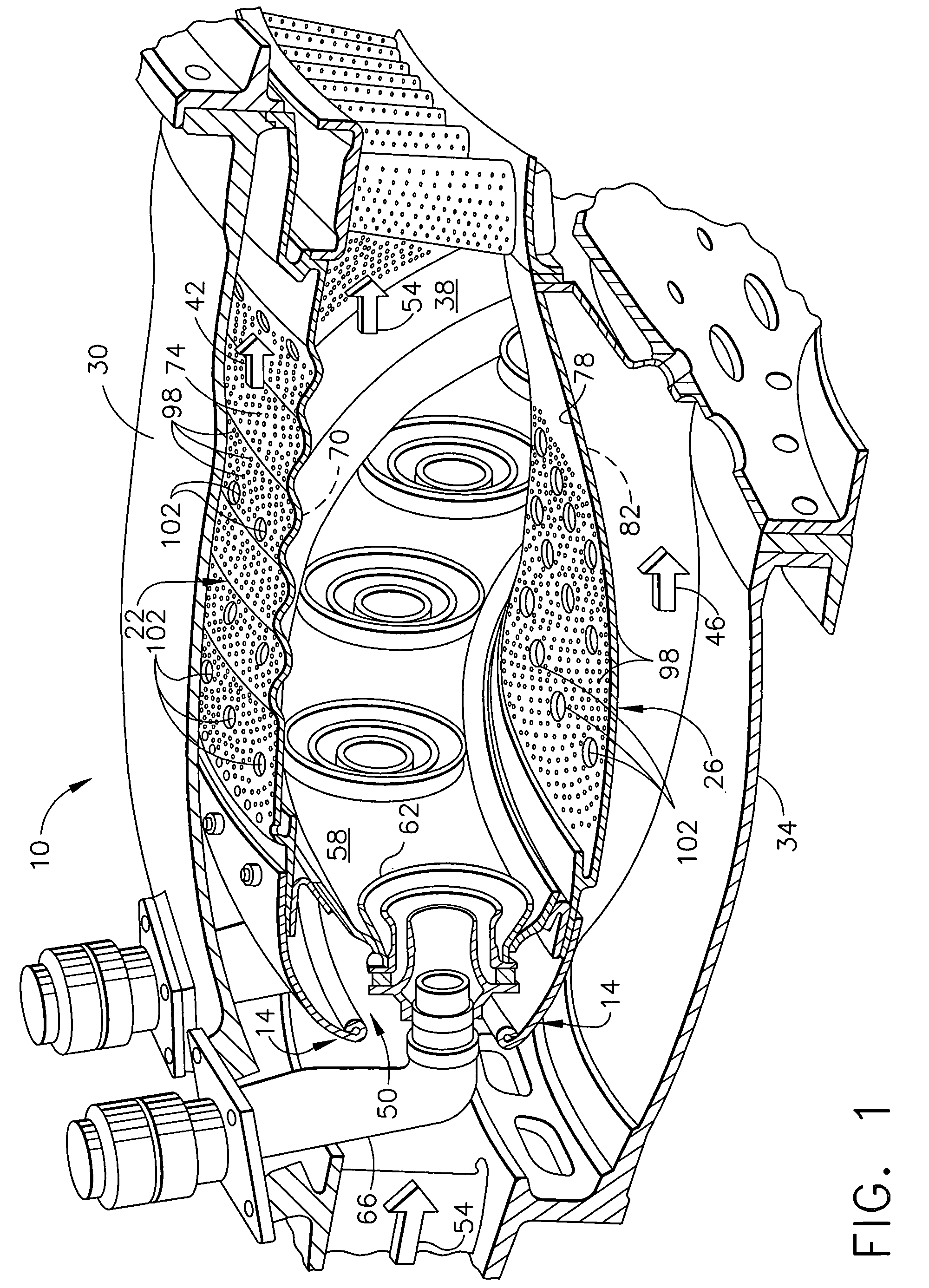
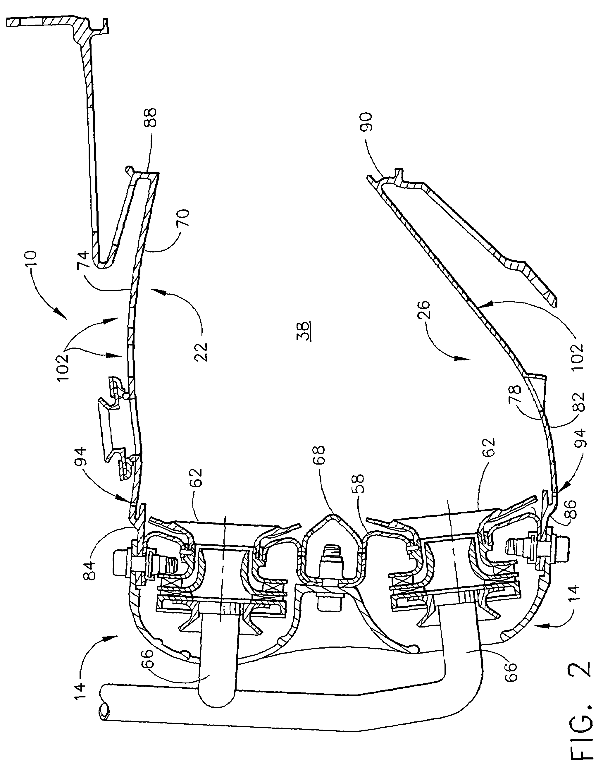
[0018]As used herein, the term “turbine component having a plurality of airflow holes” refers to any turbine engine component (e.g., gas turbine engine component) having at least two and typically a multiplicity of airflow holes through which air is circulated, typically for the purpose of cooling the component. Representative examples of such turbine components include but are not limited to turbine shrouds, such as, for example, those disclosed in commonly assigned U.S. Pat. No. 5,127,793 (Walker et al), issued Jul. 7, 1992; U.S. Pat. No. 5,169,287 (Proctor et al), issued Dec. 8, 1992; U.S. Pat. No. 6,340,285 (Gonyou et al), issued Jan. 22, 2002); and U.S. Pat. No. 6,354,795 (White et al), issued Mar. 12, 2002, all of which are incorporated by reference; combustor liners, such as, for example, those disclosed in commonly assigned U.S. Pat. No. 6,408,629 (Harris et al), issued Jun. 25, 2002; U.S. Pat. No. 6,655,149 (Farmer et al), issued Dec. 2, 2003; and U.S. Pat. No. 6,620,457 (F...


PUM

PropertyMeasurementUnit
thicknessaaaaaaaaaa
thicknessaaaaaaaaaa
diameteraaaaaaaaaa

Abstract

A method for adjusting the airflow in a turbine component having a plurality of airflow holes. The method comprises the step of depositing an overlay metallic coating on the surface of the turbine component in a manner such that at least some of the airflow holes are partially filled such that the volume of the partially filled airflow holes is changed so as to adjust the airflow through the turbine component. Also provided is a turbine component having a plurality of airflow holes, at least some of the airflow holes being partially filled with the overlay metallic coating to change the volume thereof so as to adjust the airflow through the turbine component.

Description

BACKGROUND OF THE INVENTION[0001]This invention relates to adjusting the airflow in turbine components, e.g., gas turbine components, having airflow holes by depositing an overlay metallic coating. This invention further relates to the turbine component whose airflow has been adjusted by depositing such an overlay metallic coating.[0002]Airflow holes are formed in many gas turbine components, such as combustor liners, for transporting film air through the component to typically cool the component and to form a fluid barrier between the component and hot gases traveling in the main flowpath of the engine. In addition to flowing air over the hot surfaces, combustor liner cooling is also provided by a thin layer of cooling air along the inner, combustion side of the liner by directing airflow through an array of very small airflow holes formed in the liner, typically having a diameter of from about 0.02 to about 0.03 inches (from about 508 to about 762 microns). This film cooling is al...

Claims


Application Information

Patent Timeline
Patent Type & Authority Patents(United States)
IPC IPC(8): F02C1/00
CPCF23R3/06B23P2700/06Y10T29/49341F23R2900/03042
Inventor CALDWELL, JAMES MICHAELTOMLINSON, THOMAS JOHNZIMMERMAN, JR., ROBERT GEORGEHEIDORN, RAYMOND WILLIAMFARMER, GILBERT
Owner GENERAL ELECTRIC CO
Why Eureka
Try Eureka