Electric wire changing device for wire replacing works on electric poles and power distributing method without cutting off power supply

a technology for electric poles and wires, which is applied in the direction of lighting support devices, washstands, hoisting equipment, etc., can solve the problems of uninterruptible use of 5,000 kw load, waste of time and labor costs for switching power load, and group activities and judicial cases, etc., and achieves the effect of convenient inserting and mounting

Inactive Publication Date: 2007-05-15
DAEWON ELECTRONICS CO LTD
View PDF10 Cites 29 Cited by
  • Summary
  • Abstract
  • Description
  • Claims
  • Application Information

AI Technical Summary

Benefits of technology

[0010]Another objective of the present invention is to provide a wire changing device comprising a fastening unit having a pair of the mounting frames formed with a square shape of four flat bar members, an open-able side member for easily inserting and mounting to the cross-arm, and a fastening bolt located at a bottom member for tightening on the cross-arm. The wire replacing unit consists of a supporting arm formed a cylindrical shape of two-stage extendable column, which is made of insulating material. The wire pulling unit has a plurality of rollers with a fully open-able lower member that is mounted at a ton of the supporting arm. An adjusting clamp is mounted adjacent to a step of two-stage extendable column for adjusting its height or length and tightening the column. A pair of eye bolts is disposed opposite sides on the adjusting clamp for connecting the ropes. The axial-rotating unit consists of the central arm fixture formed a flat lateral base at both opposite sides, and the arm coupling for tightly mounting the supporting arm. The axial shaft is integrally attached to the flat lateral base. An axial coupling has an inner spline. A shaft coupling is mounted on the axial shaft. A position locker has an outer spline for mating to the inner spline and an end flange integrally attached to the outer spline for coupling to the axial coupling.

Problems solved by technology

As the level of user needs for the quality of electricity increases, even an instantaneous service interruption becomes the target of a civil disruption, and electricity users' group activities and judicial cases are being increased.
Moreover, in the case where the distribution line has an electric capacity of more than 5,000 KW, since the permissible capacity of a cable in the previous bypass cable method is under 5,000 KW, this wastes a lot of time and labor cost for switching the power load to another distribution line in order to reduce the load of the distribution line to less than 5,000 KW.
Because a large capacity distributing method is used commonly, part of the load is switched and only the load of 5,000 KW is put into use uninterruptibly.
This results in an insufficient effect of investment money and there occurs a serious problem in effectively operating the distribution network.
In addition, it is impossible to construct a distribution line with more than two lines, i.e. upper and lower lines, per one pole by the existing temporary power transmission type interruptible method.
Therefore, for the above-described previous distribution maintenance using the uninterruptible method, a lot of construction workers are required.
Also, a large number of temporary connection points of an extra high voltage, which are very dangerous, are made in order to install a bypass cable with a specified length of 50 m. This requires the use of protective equipment for connection failures and connection points.
Because installation and removal tasks have to be repeated often, a lot of labor cost is required and the damage to the bypass cable is accelerated, thus threatening safety.
If there occurs an accident or unexpected interruption, this costs a great deal, thus making it difficult to secure a good electricity quality.
Also, this may cause more civil applications, economic losses and loss of life.
Moreover, excessive load switching operations make the functioning of the distribution network unstable and the upper end line of a distribution line with more than two lines cannot be serviced with the uninterruptible method.

Method used


Image

  • Electric wire changing device for wire replacing works on electric poles and power distributing method without cutting off power supply
  • Electric wire changing device for wire replacing works on electric poles and power distributing method without cutting off power supply
  • Electric wire changing device for wire replacing works on electric poles and power distributing method without cutting off power supply

Examples


Embodiment Construction

[0032]Hereinafter, in order to achieve the aforementioned technical objectives, a wire changing device will be described in detail accompanying with the drawings.

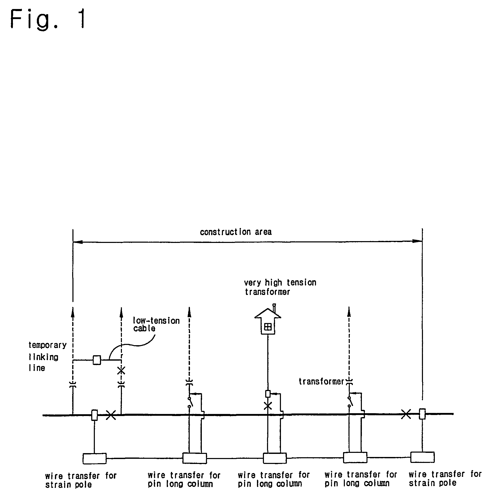
[0033]As shown in FIG. 1, a wire distribution and deployment at the electrical working site is adopting the uninterruptible method of the present invention. A new concept of technique of wire changing device is employed without using the conventional methods of transportable transformer, the bypassing cable or the break switching.

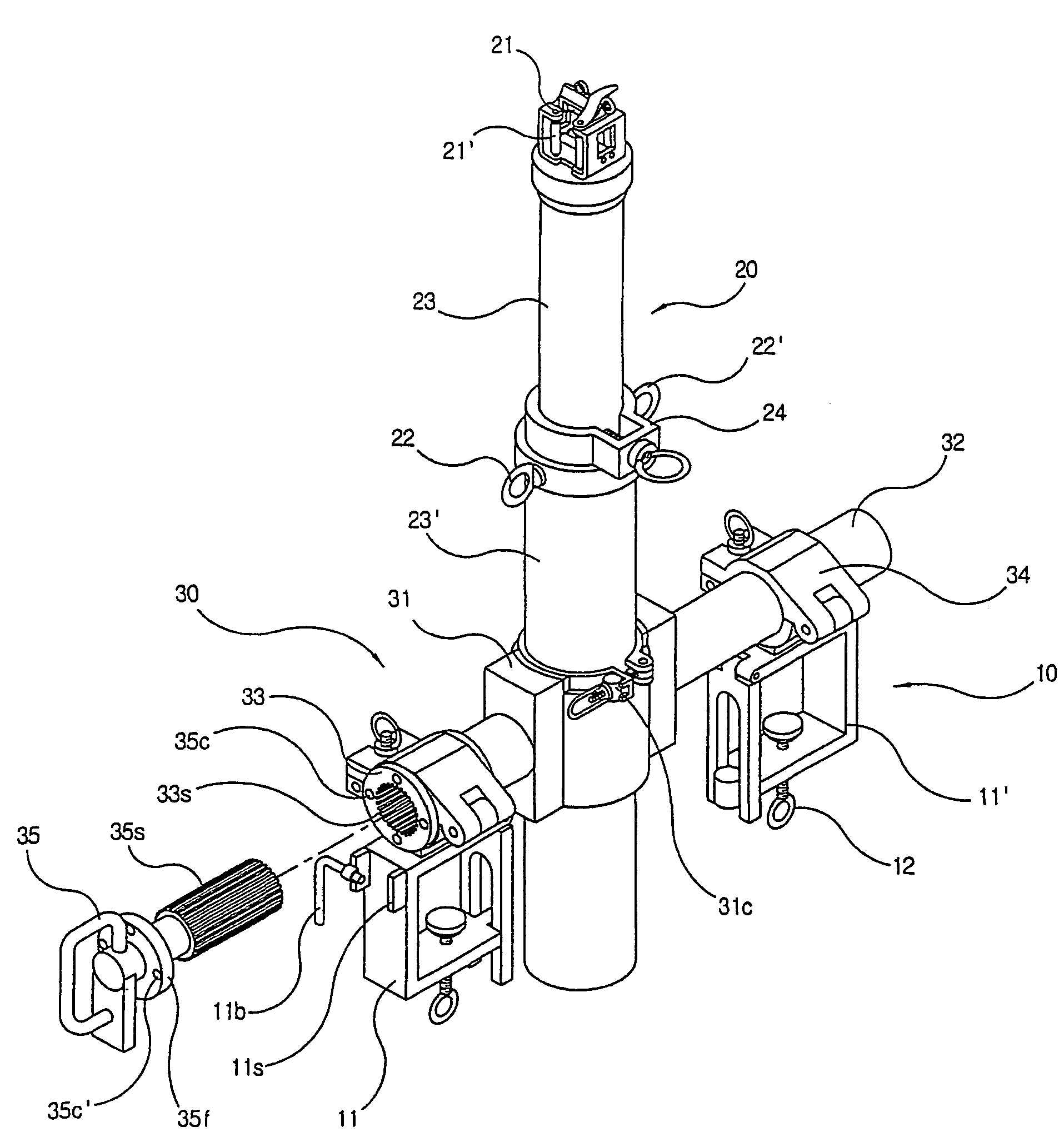
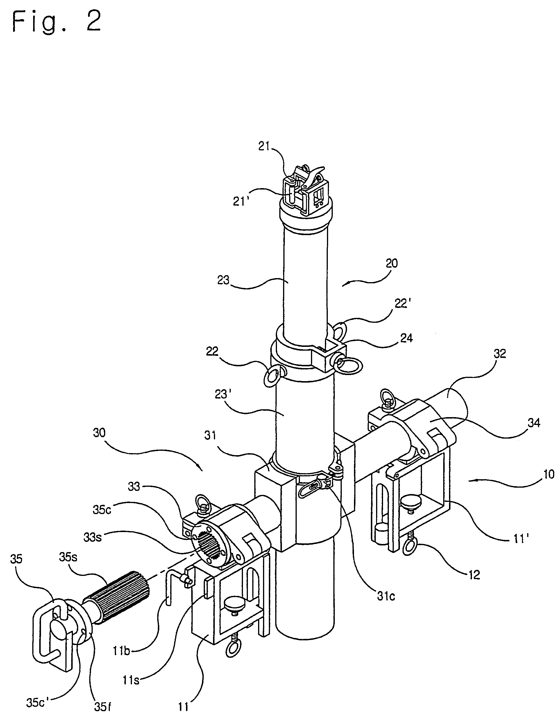
[0034]A device for changing a live electric wire mounted on the electric poles at the working site is used without cutting off power supply. The device is comprising: a fastening unit (10) having a mounting frame for mounting and tightening the device on a cross-arm of the electric pole, a wire replacing unit (20) having a supporting arm for installing and removing the live electric wire and pulling to adjust the wire tension, and an axial-rotating unit (30) having a central arm fixture, an arm cou...


PUM


Abstract

A device for changing an electric wire and method for distributing power without cutting off power supply has developed for replacing the live electric line on the electric poles, relocating the electric poles and alteration of the power distribution route. Replacement operation of the live electric wire is sequentially performed by connecting new wire and separating old wire by the wire changing device mounted on each electric pole without using bypass cable. The wire changing device comprises a cross-arm fastening unit, wire replacing unit and axial-rotating unit having a central arm fixture, axial shaft, arm coupling and position locking unit. The wire changing method comprises the steps of: mounting the wire changing device on each electric pole, replacing new and old wires without cutting off power supply, arranging the wire space, installing and tightening the new wire on each LP insulator of the electric pole, and removing the separated wire.

Description

BACKGROUND OF THE INVENTION[0001]1. Field of the Invention[0002]The present invention relates to a device for changing the electric wires and method for distributing power without cutting off power supply during the replacing work of the live electric lines on the electric poles, relocating work of the electric poles and alteration work of the power distribution route. The replacing operation of live electric wires is sequentially carried out by connecting the new wire and separating the old wire by the wire changing device mounted on each electric pole without using a bypass cable.[0003]2. Related Prior Art[0004]With rapid increase of power demand, power facilities to satisfy this demand are being expanded continuously. As the level of user needs for the quality of electricity increases, even an instantaneous service interruption becomes the target of a civil disruption, and electricity users' group activities and judicial cases are being increased. To supply power of good quality ...

Claims


Application Information

Patent Timeline
Patent Type & Authority Patents(United States)
IPC IPC(8): H02G1/02B66D3/08
CPCH02G1/02
Inventor KWON, SAE-WON
Owner DAEWON ELECTRONICS CO LTD
Why Eureka
Try Eureka