Perpendicular magnetic recording medium and magnetic recording/reproducing apparatus

a magnetic recording medium and perpendicular magnetic technology, applied in the direction of magnetic recording, data recording, instruments, etc., can solve the problems of unidirectional production and inability to prevent neighboring track erasure, so as to prevent the fluctuation of readback output and the decay of magnetization or the erasure of recorded magnetization in the recording layer

Inactive Publication Date: 2007-05-15
HITACHI GLOBAL STORAGE TECH JAPAN LTD
View PDF3 Cites 11 Cited by
  • Summary
  • Abstract
  • Description
  • Claims
  • Application Information

AI Technical Summary

Benefits of technology

[0010]In the perpendicular magnetic recording medium and the magnetic recording/reproducing apparatus of the present invention configured as described above, magnetic domains in the soft magnetic underl

Problems solved by technology

However, the method for producing unidirectional magnetization of the soft magnetic layer, using the hard magnetic pinning layer, makes it easy to form magnetic domains in a reverse direction around the inner and outer edges of the disk substrate, from where spike noise is observed.
The method f

Method used


Image

  • Perpendicular magnetic recording medium and magnetic recording/reproducing apparatus
  • Perpendicular magnetic recording medium and magnetic recording/reproducing apparatus
  • Perpendicular magnetic recording medium and magnetic recording/reproducing apparatus

Examples


embodiment 1

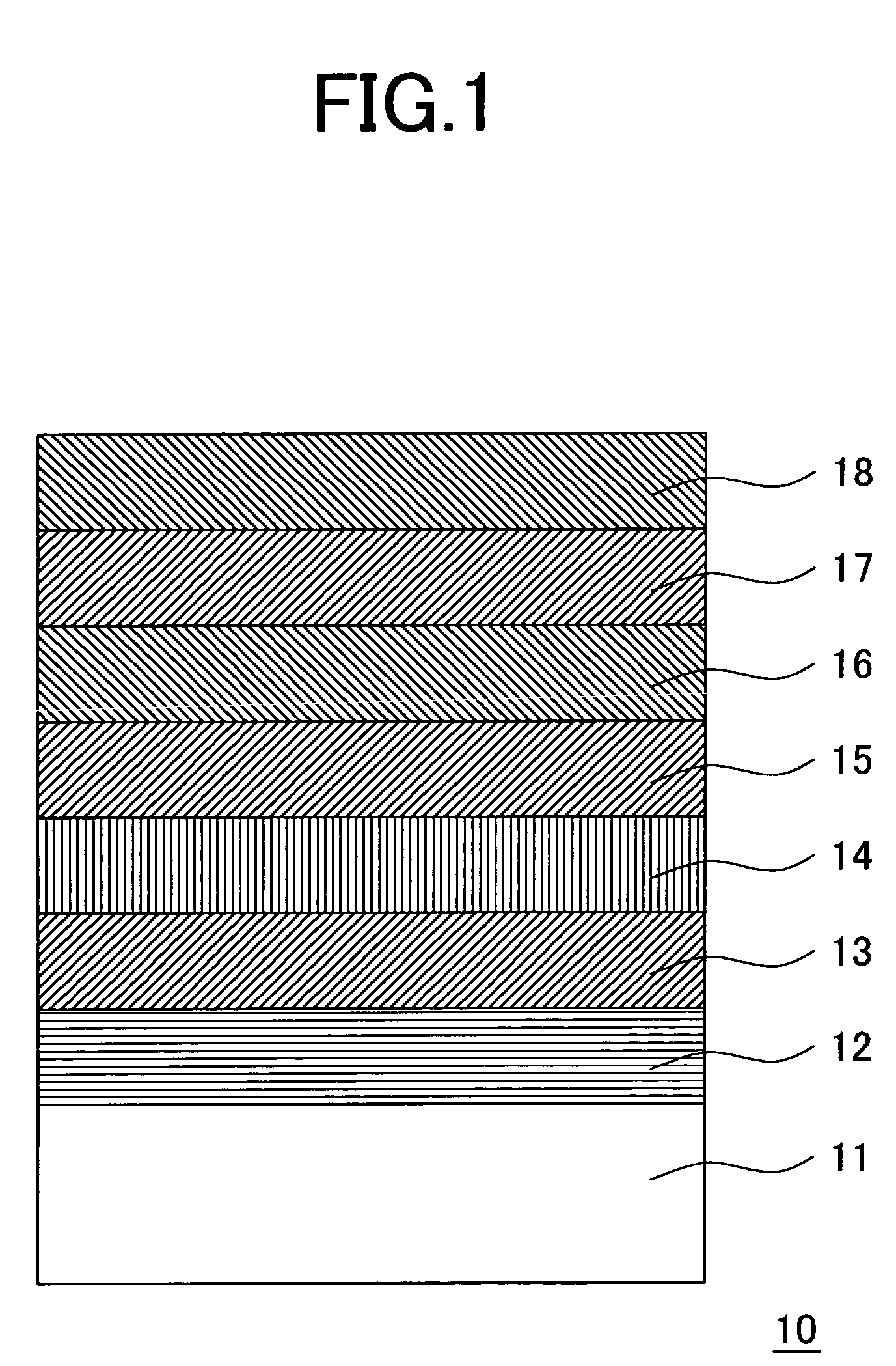
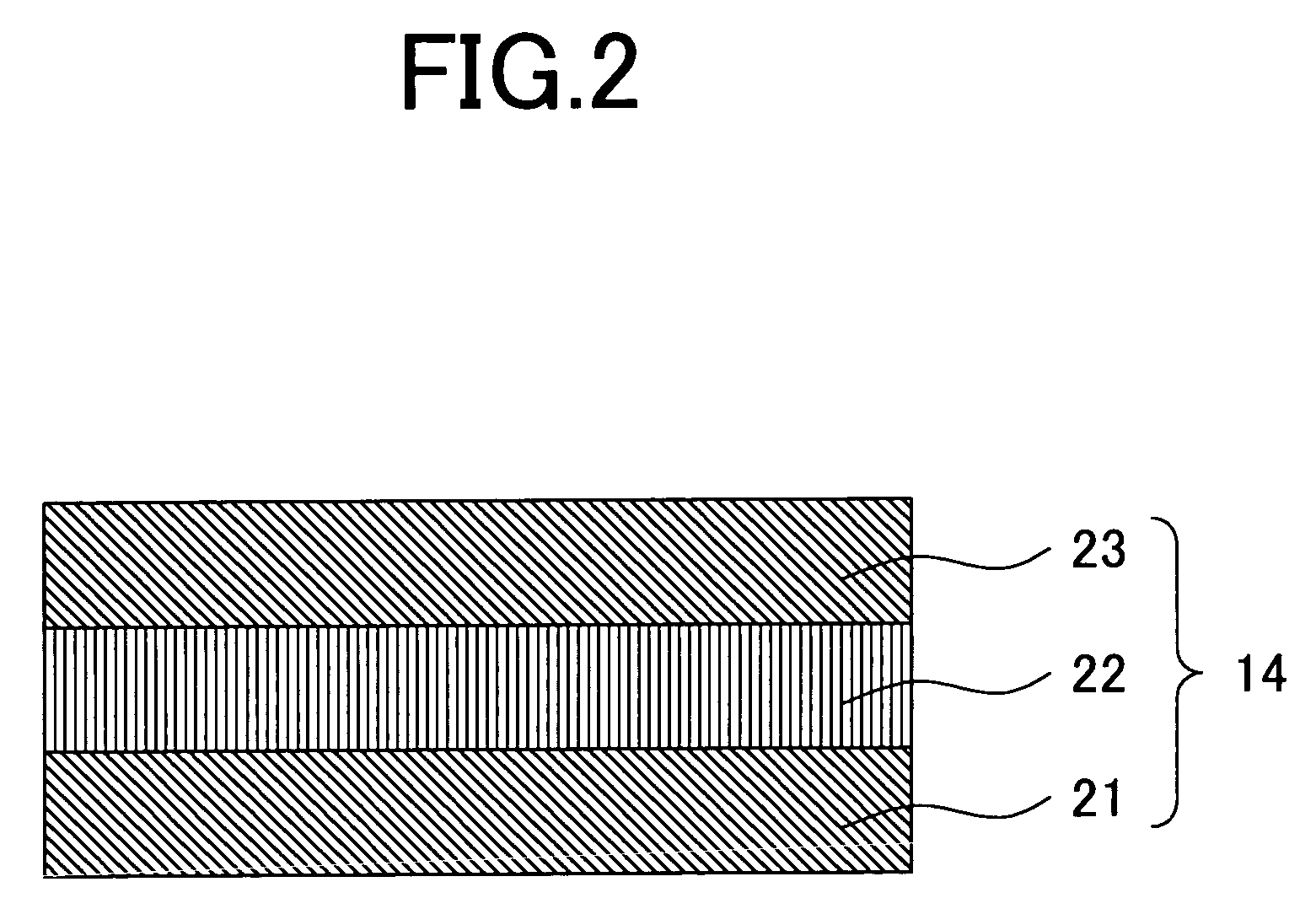
[0051]FIG. 1 shows a layer structure of a perpendicular recording medium 10 according to a preferred Embodiment 1 of the invention. For a substrate 11, a glass substrate with a diameter of 2.5 cm, after cleaned by alkali washing, was employed. On the substrate, a precoat layer 12 for ensuring a tight contact with the substrate 11, a first soft magnetic layer 13, a domain control layer 14, a second soft magnetic layer 15, an intermediate layer 16, a recording layer 17, and an overcoat layer 18 were formed in sequence by DC magnetron sputtering. The domain control layer 14 has a triple-layered structure consisting of a first ferromagnetic layer 21, anti-ferromagnetic layer 22, and second ferromagnetic layer 23, as is shown in FIG. 2. Table 2 lists target compositions employed per layer, Ar gas pressure during deposition, and layer thickness.

[0052]

TABLE 2TargetAr gasThicknesscompositionpressure (Pa)(nm)Precoat layer 12Ni52.5Ta37.5Zr101301st soft magnetic layer 13Ni81Fe190.525–2001st fe...

embodiment 2

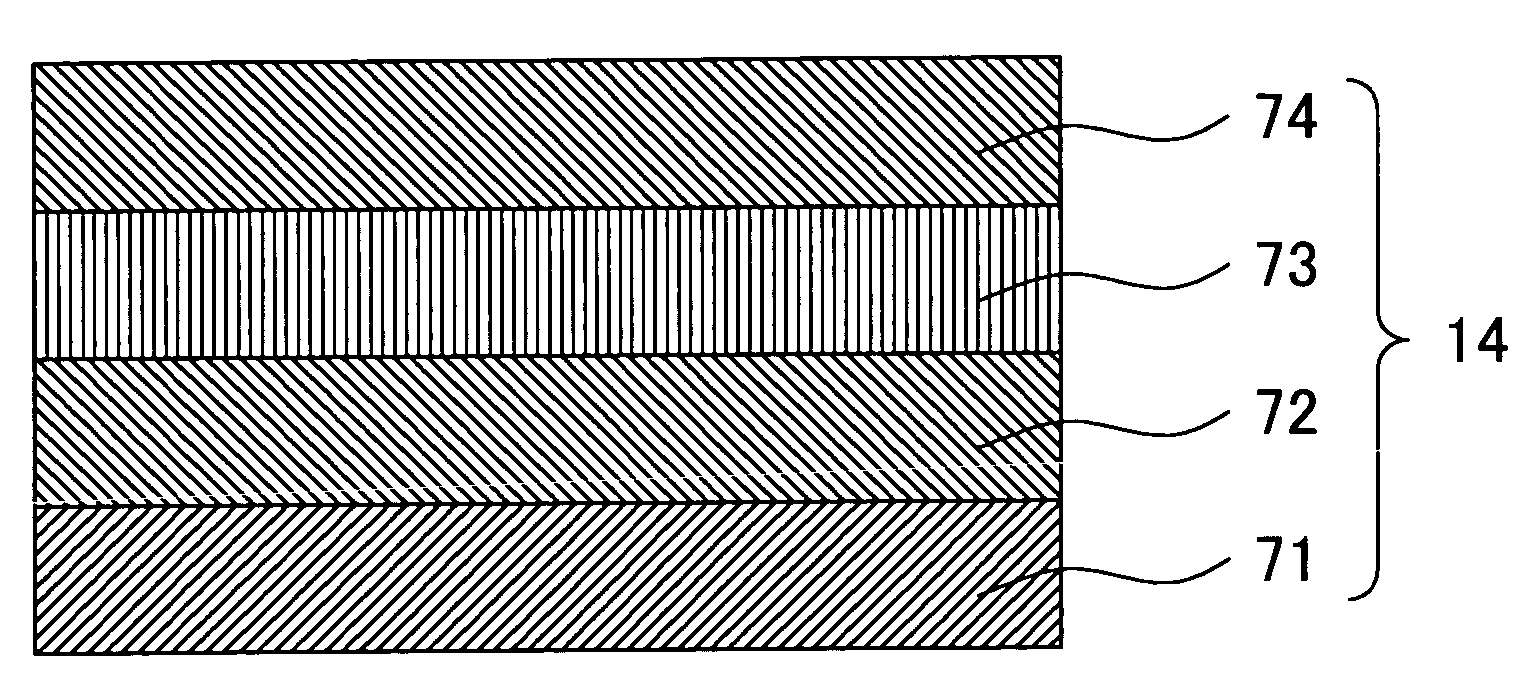
[0064]A medium 10 having the same layered structure as the perpendicular recording medium of Embodiment 1 was produced, wherein the first soft magnetic layer 13 and second soft magnetic layer 15 are made of an amorphous alloy. In a preferred Embodiment 2, the domain control layer 14 is comprised of a soft magnetic seed layer 71, first ferromagnetic layer 72, anti-ferromagnetic layer 73, and second ferromagnetic layer 74 which are deposited in order of mention, as shown in FIG. 7. Table 3 lists target compositions employed per layer, Ar gas pressure, and layer thickness. The referential medium 170 shown in FIG. 17 was produced by employing the same target compositions and on the same deposition conditions as for Embodiment 2.

[0065]

TABLE 3TargetAr gasThicknesscompositionpressure (Pa)(nm)Precoat layer 12Ni52.5Ta37.5Zr101301st soft magnetic layer 13Co92Ta3Zr50.520–150Soft magnetic seed layer 71Ni81Fe190.551st ferromagnetic layer 72Co70Fe300.52.5Anti-ferromagnetic layer 73Mn80Ir201102nd ...

embodiment 3

[0071]A medium having the same layered structure as the perpendicular recording medium of Embodiment 1 was produced, wherein the first soft magnetic layer 13 is made of a crystalline alloy and the second soft magnetic layer 15 is made of an amorphous alloy. In a preferred Embodiment 3, the domain control layer is comprised of a ferromagnetic layer 121 and anti-ferromagnetic layer 122 which are deposited in order of mention, as shown in FIG. 12. Table 4 lists target compositions employed per layer, Ar gas pressure, and layer thickness.

[0072]

TABLE 4TargetAr gasThicknesscompositionpressure (Pa)(nm)Precoat layer 12Ni52.5Ta37.5Zr101301st soft magnetic layer 13Ni46Fe540.5100Ferromagnetic layer 121Co70Fe300.55Anti-ferromagnetic layerMn80Ir201101222nd soft magnetic layer 15Fe52Co28B200.590Intermediate layer 16Ru120Recording layer 17CoCr13Pt14SiO2120Overcoat layer 18Carbon15

[0073]On the substrate, the precoat layer 12 of NiTaZr, first soft magnetic layer 13 of NiFe, first ferromagnetic layer...


PUM


Abstract

A magnetic recording/reproducing apparatus is disclosed with high storage capability. The apparatus also prevents fluctuation of readback output and decay of magnetization or erasure of recorded magnetization in the recording layer. A soft magnetic underlayer and a perpendicular recording layer are formed in specific order on the substrate of a magnetic disk. The soft magnetic underlayer has a triple-layered structure in which a domain control layer, including an anti-ferromagnetic layer, is sandwiched between two first and second soft magnetic layers. The thickness of the first and second soft magnetic layers (d1, d2) is between 25 nm and 150 nm and a ratio of d1/d2 is within a range of 0.3 to 1.5. Accordingly, magnetic domains in the soft magnetic underlayer of a perpendicular magnetic recording medium can be controlled and magnetic domain wall motion can be inhibited.

Description

BACKGROUND OF THE INVENTION[0001]In recent years, an areal recording density of magnetic disk storage devices (disk drives) has soared at an annual growth rate of about 100%. Meantime, a so-called thermal fluctuation problem is emerging; that is, as the areal recording density becomes higher and higher, magnetically recorded data is erased by surrounding heat. Storage researchers think it is difficult to achieve the areal recording density over 7.75 Gbits per square centimeter on a magnetic drive by conventional longitudinal recording.[0002]Meanwhile, a perpendicular recording method, unlike the longitudinal recording method, has a feature that, as linear recording density increases, a demagnetizing field acting between adjacent bits decreases, and recording magnetization keeps stable. Moreover, a soft magnetic underlayer having a high magnetic permeability formed under a perpendicular recording layer enables magnetic heads to generate a high magnetic field and, consequently, the co...

Claims


Application Information

Patent Timeline
IPC IPC(8): G11B5/667G11B5/673G11B5/00G11B5/65G11B5/73
CPCG11B5/667G11B5/732G11B2005/0029G11B5/7379
Inventor ARAI, REIKOTANAHASHI, KIWAMUKIKUGAWA, ATSUSHI
Owner HITACHI GLOBAL STORAGE TECH JAPAN LTD
Why Eureka
Try Eureka