Fan motor speed control circuit

a technology of speed control circuit and fan motor, which is applied in the direction of motor/generator/converter stopper, electric controller, dynamo-electric converter control, etc., can solve the problem that the conventional fan motor rotation speed control circuit cannot avoid the noise problem caused, and achieve the effect of reducing vibration degree and noise problem

Active Publication Date: 2007-05-15
DELTA ELECTRONICS INC
View PDF9 Cites 19 Cited by
  • Summary
  • Abstract
  • Description
  • Claims
  • Application Information

AI Technical Summary

Benefits of technology

[0007]In order to solve this problem, this invention discloses a fan motor speed control circuit that reduces the above-mentioned noises and smoothens the speed change of the fan motor.
[0011]The advantage of this invention is to reduce the vibration degree and noise problem occurred in a conventional fan motor control circuit directly driven by an external low frequency PWM signal.

Problems solved by technology

A conventional fan motor rotation speed control circuit cannot avoid the noise problem caused by the ON / OFF switch of the fan motor when the frequency of a pulse width modulation (PWM) signal is low.

Method used


Image

  • Fan motor speed control circuit
  • Fan motor speed control circuit
  • Fan motor speed control circuit

Examples


Embodiment Construction

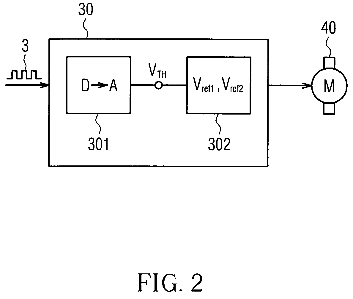
[0020]Referring to FIG. 2, a fan motor speed control circuit 30 in accordance with the invention comprises a digital / analog converting unit 301 and a driving unit 302. The digital / analog converting unit 301 is used for converting an inputted PWM digital signal 3 into an analog signal such as a voltage signal. The driving unit 302 takes the analog signal and compares it with two predetermined voltages Vref1 and Vref2 set by the driving unit. After that, a digital signal representing the comparison result is used to control the rotation speed of the fan motor 40.

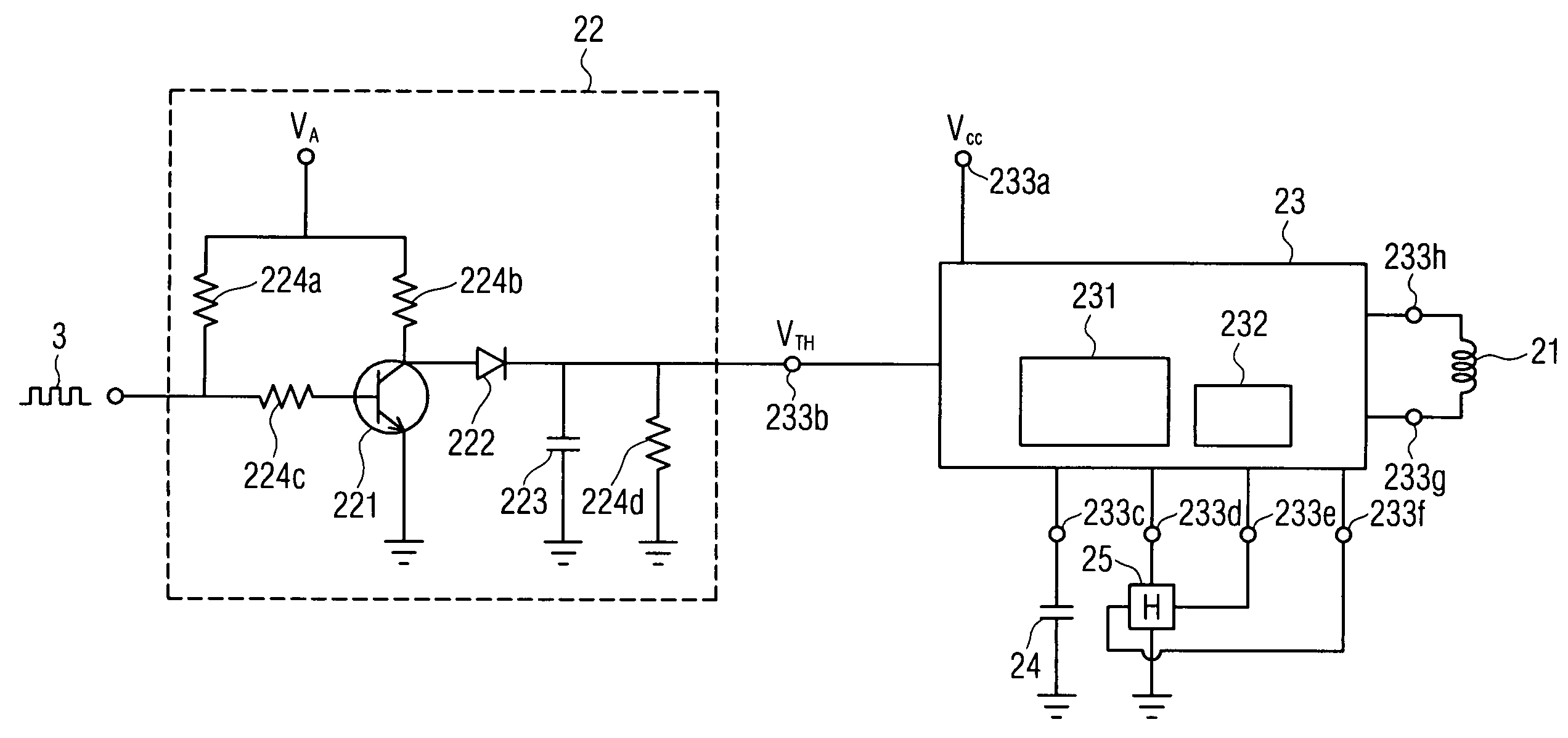
[0021]The fan motor speed control circuit according to one embodiment of the invention is shown in FIG. 3A. In this embodiment, a digital / analog converting circuit 22 is employed as a digital / analog converting unit, and a drive IC 23 is employed as a driving unit. In this embodiment, the digital / analog converting circuit 22 is mainly composed of a transistor 221, a diode 222, a capacitor 223, and a plurality of resistors 224a˜...


PUM


Abstract

A fan motor speed control circuit is disclosed. The circuit includes a digital / analog converting unit and a driving unit. The digital / analog converting unit takes charge of receiving a pulse width modulation (PWM) signal and converting it into a voltage signal. The driving unit is connected with the digital / analog converting unit in series for receiving the voltage signal, while the driving unit provides a first predetermined voltage level and a second predetermined voltage level as references. The fan motor is kept to run with a low constant rotation speed when the voltage signal level is higher than the first predetermined voltage level, with a full constant rotation speed when the voltage signal level is lower than the second predetermined voltage level, and with a variable rotation speed when the voltage signal level is lower than the first predetermined voltage level and higher than the second predetermined voltage level.

Description

[0001]This nonprovisional application claims priority under 35 U.S.C. § 119(a) on Patent Application No. 092119947 filed in TAIWAN on Jul. 22, 2003, the entire contents of which are hereby incorporated by reference.BACKGROUND OF THE INVENTION[0002]This invention relates to a rotation speed control circuit, and more particularly to a fan motor speed control circuit.DESCRIPTION OF RELATED ART[0003]With respect to fan motor speed control techniques, it is well known that people skilled in the art often uses a control circuit being composed of various type of transistors and driving integrated circuit (IC) chips, and an external driving signal for the control circuit, such as a pulse width modulation (PWM) signal, to control the rotation speed of a fan motor.[0004]Referring to FIG. 1A, in a conventional fan motor rotation speed control technique, an external pulse width modulation (PWM) signal 3 is mainly used to drive a bipolar transistor 2 and a drive IC 5, in order to control the ter...

Claims


Application Information

Patent Timeline
Patent Type & Authority Patents(United States)
IPC IPC(8): G05B11/28F04D27/02H02P6/08H02P6/06H03K17/60
CPCF04D27/004Y02B30/70
Inventor HUANG, WEN-SHITSAI, MING-SHILIU, CHENG-CHIEHHSIEH, TSUNG-JUNGHUANG, YUCH-LUNG
Owner DELTA ELECTRONICS INC
Why Eureka
Try Eureka