

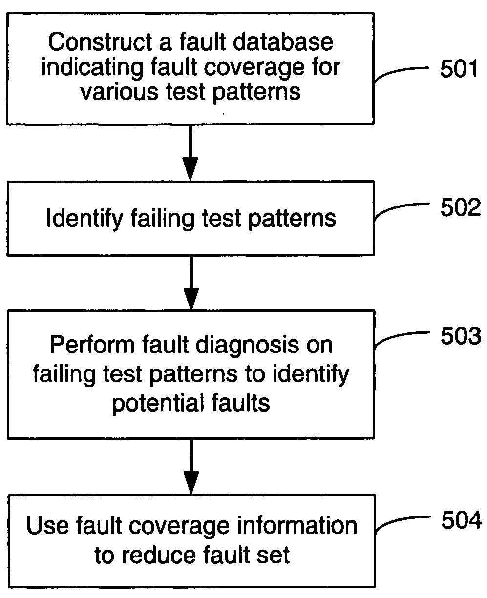
Automated fault diagnosis in a programmable device
a programmable device and fault diagnosis technology, applied in the field of semiconductor circuit testing, can solve the problems of inability to solve fault diagnosis approaches for complex ic devices, the size of the fault dictionary may be exceedingly large, and the node to undesirably remain, so as to reduce the set of potential faults, reduce the time required, and reduce the fault set
- Summary
- Abstract
- Description
- Claims
- Application Information
AI Technical Summary
Benefits of technology
Problems solved by technology
Method used
Image

Examples
Embodiment Construction
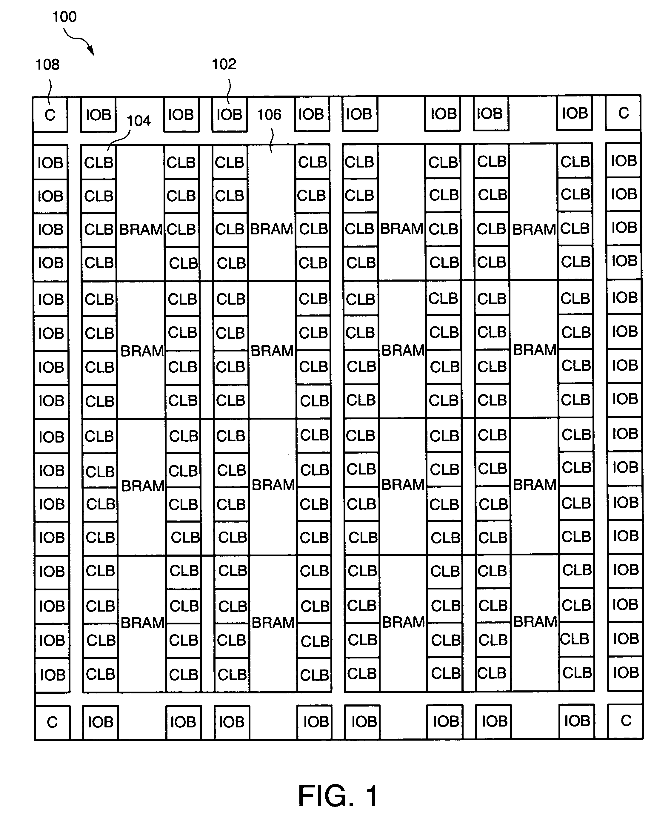
[0022]Embodiments of the present invention are described below with respect to an exemplary FPGA architecture that is generally representative of the Virtex family of FPGA devices from Xilinx, Inc., for simplicity only. It is to be understood that embodiments of the present invention are equally applicable other FPGA architectures, and to other programmable devices, including programmable logic devices such as complex PLDs and integrated circuits that are at least partially programmable. In the following description, for purposes of explanation, specific nomenclature is set forth to provide a thorough understanding of the present invention. In other instances, well-known circuits and devices are shown in block diagram form to avoid obscuring the present invention. Further, the particular order in which embodiments of the present invention are performed may be altered. Accordingly, the present invention is not to be construed as limited to specific examples described herein but rathe...
PUM
 Abstract
Description
Claims
Application Information