
High performance CRC calculation method and system with a matrix transformation strategy

a matrix transformation and calculation method technology, applied in the field of crc calculation, can solve the problems of increasing the number of hardware required, increasing the cost, size and complexity, and reducing reliability, and achieve the effect of simplifying the crc calculation and simplifying the circuitry of the system

Active Publication Date: 2007-05-15
MACRONIX INT CO LTD
View PDF1 Cites 48 Cited by
  • Summary
  • Abstract
  • Description
  • Claims
  • Application Information

AI Technical Summary

Benefits of technology

The present invention is about a way to make the CRC (cyclic redundancy check) calculation faster and simpler. It uses a linear mapping matrix to generate the CRC, and a transformation matrix to reduce the maximum value of non-zero entries in the mapping matrix. The input messages are padded with specific dummies, and the CRC outputs are compared with specific patterns for the doubleword-wise CRC32 case. This method and system speed up the CRC generation process and simplify the circuitry of the system.

Problems solved by technology

The drawback of hardware implementation of CRCs is that more hardware is required with consequent increase in cost, size and complexity and a decrease in reliability.
Software implemented CRCs are known although their use is not widespread because of the speed penalty thought to be inevitable.
Those skilled in the art understand that choosing a polynomial of a larger degree will result in greater error detection.
However, for the applications of current large scale systems, the desired hardware becomes too complicated and costly to be implemented and the required software needs huge computations.
These CRC routines are considered to be the fastest software implementations available, but they take up a great deal of dedicated memory.
However, the serial processing for the generation of the CRC is relatively slow, and as the technology advanced, single-bit CRC generation was not enough to handle high-speed data processing and transmission, and parallel CRC algorithms were then developed to meet this need.

Method used


Image

  • High performance CRC calculation method and system with a matrix transformation strategy
  • High performance CRC calculation method and system with a matrix transformation strategy
  • High performance CRC calculation method and system with a matrix transformation strategy

Examples


Embodiment Construction

Cyclic Code in a Systematic Form

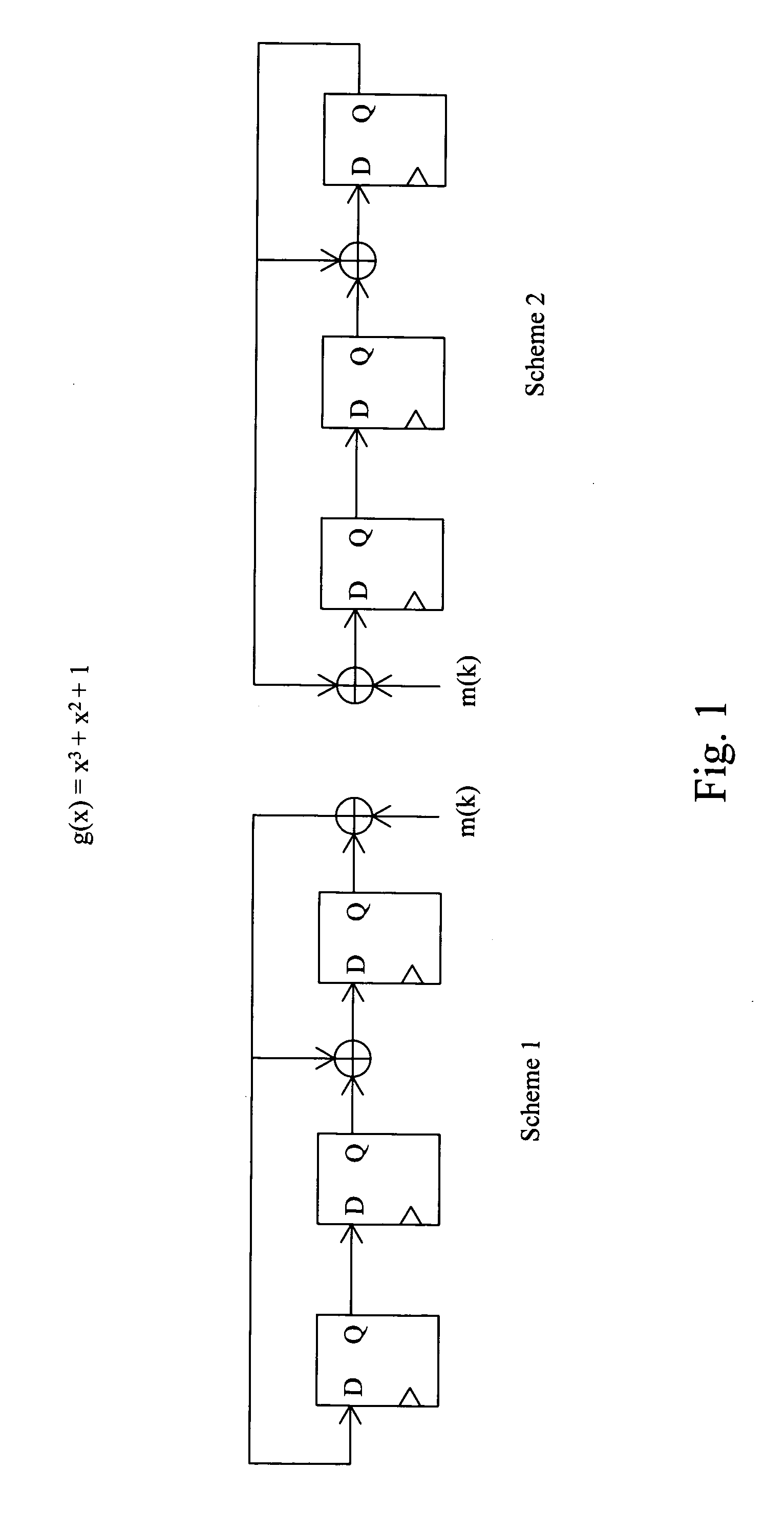
[0026]As is well-known, an (n, k) linear code C is called a cyclic code if every cyclic shift of a code vector in C is also a code vector in C. To figure out a cyclic code in a systematic form on the transmission side, let the message to be encoded is

M=(mk−1 . . . m1m0)T,  (EQ-1)

and the corresponding message polynomial is

m(x)=m0xk−1+m1xk−2+ . . . +mk−2x+mk−1.  (EQ-2)

After multiplying m(x) by xn−k, equation EQ-2 becomes

xn−km(x)=m0xn−1+m1xn−2+ . . . +mk−2xn−k+1+mk−1xn−k.  (EQ-3)

Then, xn−km(x) is divided by the generator polynomial g(x), and it becomes

xn−km(x)=q(x)g(x)+r(x).  (EQ-4)

By rearranging equation EQ-4 and inversing the sign of the remainder to replace the original one, it will be obtained the codeword polynomial

xn−km(x)+r(x)=q(x)g(x).  (EQ-5)

Obviously, this codeword polynomial is divisible by the generator polynomial g(x).

[0027]From the above description, it can be summarized that a cyclic encoding in a systematic form includes:[0028]Step 1. Mul...


PUM


Abstract

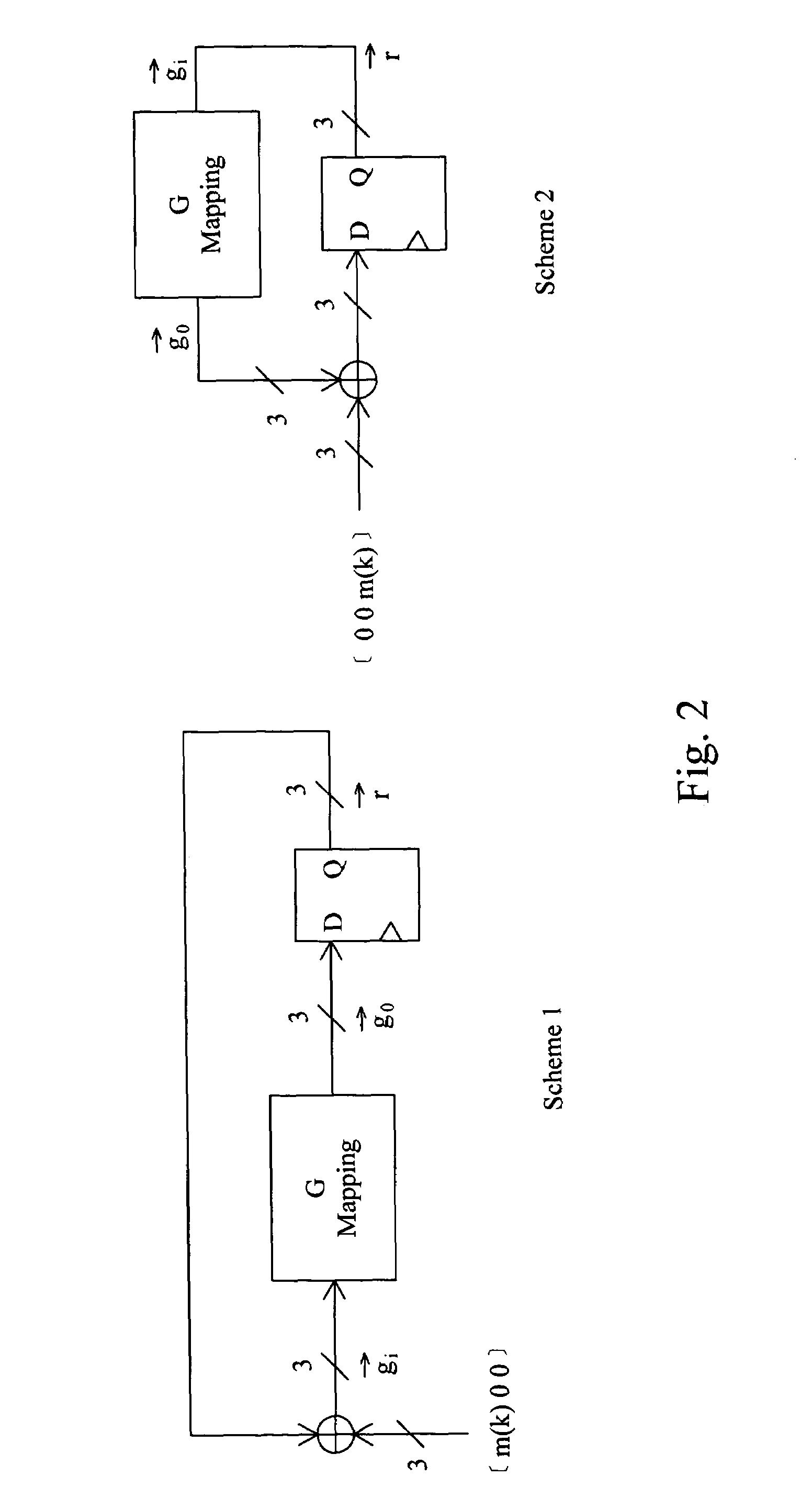
A CRC calculation method and system for generating a CRC from a message is provided while improving the process time and simple to implement. A linear mapping matrix is used for the operation of the LFSR to generate the CRC and the maximum value of the non-zero entries in the mapping matrix is reduced by applying one or more raw operations to the linear mapping matrix in advance before the computation of mapping the input message to the CRC result. Flip-flops are additionally inserted before the generator matrix to obtain a pipeline architecture so as to further improving the operation speed thereof.

Description

FIELD OF THE INVENTION[0001]The present invention relates generally to a CRC calculation, and, more particularly, to a high performance CRC calculation method and system with a matrix transformation strategy.BACKGROUND OF THE INVENTION[0002]Cyclic redundancy code (CRC) has been used for a long time to preserve the integrity of digital data in storage and transmission systems. More particularly, CRC is an important error detection tool used for communications and data processing applications. The CRC schemes are often used for checking integrity of data because they are easy to implement and they detect a large class of errors. CRC is a kind of checksum which is transmitted with data between a source node and a target node over a communications medium. The source node calculates the CRC for the data to be transferred using a predetermined polynomial and then transmits the data along with the CRC to the target node where the CRC of the received data is independently generated using th...

Claims


Application Information

Patent Timeline
Patent Type & Authority Patents(United States)
IPC IPC(8): H03M13/00H03M13/09
CPCH03M13/091H03M13/09
Inventor TSAI, KOVSKY T. J.CHANG, JOE
Owner MACRONIX INT CO LTD
Learn More