Accelerometer with cantilever and magnetic field detector

a magnetic field detector and accelerometer technology, applied in the direction of acceleration measurement in multiple dimensions, acceleration measurement using interia forces, instruments, etc., can solve the problem of estimating the error component resulting from the displacement of the magnet body caused by the torque, and achieve the effect of suppressing the influence of a peripheral magnetic field and improving the accuracy of the accelerometer

Inactive Publication Date: 2007-05-22
AICHI STEEL
View PDF17 Cites 35 Cited by
  • Summary
  • Abstract
  • Description
  • Claims
  • Application Information

AI Technical Summary

Benefits of technology

[0007]The present invention was made in consideration of the problem described above, and an object of the present invention is to provide an accelerometer for measuring the displacement of a magnet body using a magnetic sensor, in which the accuracy of the accelerometer is improved by suppressing influence of a peripheral magnetic field.
[0011]As described above, according to the accelerometer of the present invention, of the detection signal output from the magnetic detecting head portion, the error component by the direct influence of the peripheral magnetic field and the error component by the indirect influence thereof can be corrected, and hence the acting acceleration can be accurately measured.
[0016]In an acceleration sensing part, in order to improve the sensing sensitivity, the rigidity of the cantilever is decreased as much as possible so that the deformation can be more easily obtained. Accordingly, when the acceleration sensing part is handled, the cantilever which is easily deformed and the magnet body fixed to the free end of the cantilever must be prevented from being touched.
[0017]Hence, in the acceleration sensing part of the present invention, the support member is composed of the base portion and the extending portion. By this structure, while the cantilever and the magnet body are prevented from being touched, the support member can be easily held, and hence the handling of the acceleration sensing part becomes easier. For example, when the acceleration sensing part is mounted onto a substrate or the like, the handling can be easily performed.
[0018]In addition, as a result, an acceleration sensing part having superior sensing accuracy can be obtained.

Problems solved by technology

In addition, of the detection signal output from the magnetic detecting head portion, an error component resulting from the displacement of the magnet body caused by the torque can be estimated.

Method used


Image

  • Accelerometer with cantilever and magnetic field detector
  • Accelerometer with cantilever and magnetic field detector
  • Accelerometer with cantilever and magnetic field detector

Examples


embodiment

Embodiment 1

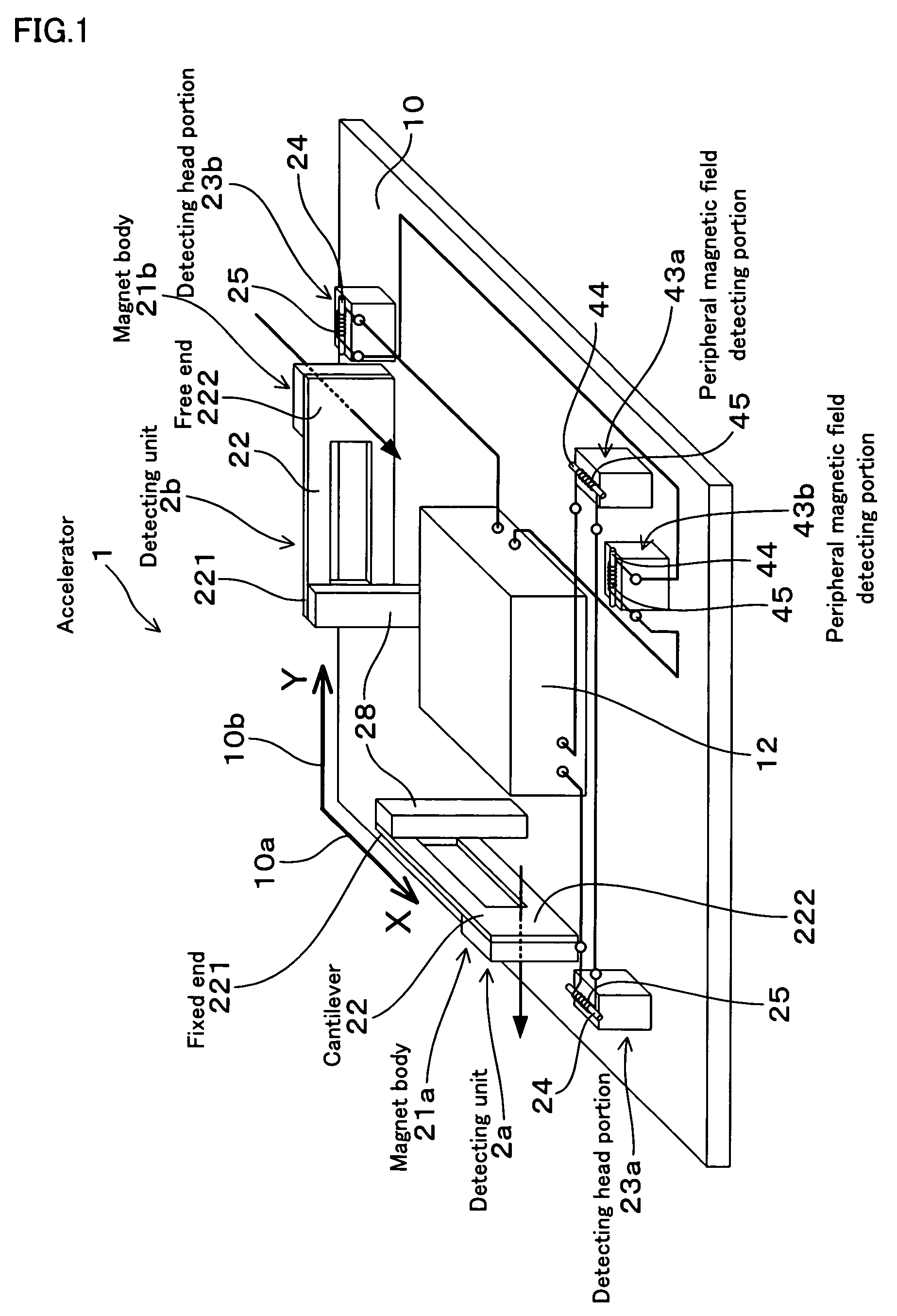
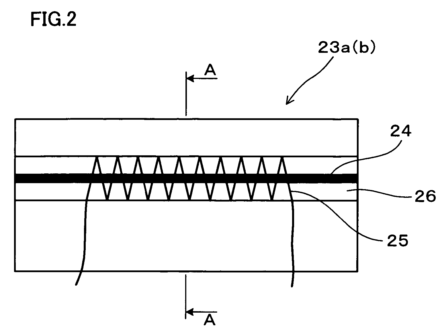
[0104]In this embodiment, an accelerometer 1 will be described which uses an amorphous wire as a magnetic sensing member 24. The structure will be described with reference to FIGS. 1 to 8.

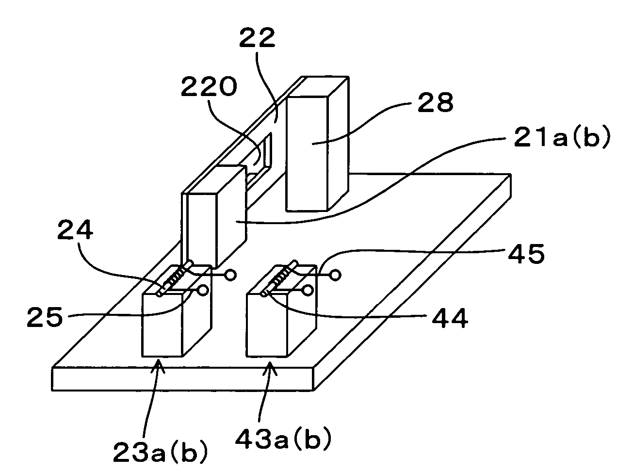
[0105]As shown in FIG. 1, the accelerator 1 of this embodiment includes detecting unit 2a (2b) having a cantilever 22 to be elastically deformed so as to rotate around a fixed end 221 thereof, a magnet body 21a (21b) provided at a free end 222 of the cantilever 22, and a magnetic detecting head portion 23a (23b) disposed outside the rotation region of the cantilever 22.

[0106]In order to correct detection signals output from the magnetic detecting head portions 23a and 23b, this accelerometer 1 has peripheral magnetic field detecting portions 43a and 43b for measuring a peripheral magnetic field applied to the magnetic detecting head portions 23a and 23b and magnet bodies 21a and 21b.

[0107]Hereinafter, the structure will be further described in detail.

[0108]As shown in FIG. 1, the accel...

embodiment 2

[0141]In this embodiment, the case in which the structure of the peripheral magnetic field detecting portion and that of the IC chip are different from that in Embodiment 1 will be described with reference to FIGS. 11 to 14.

[0142]As shown in FIG. 11, the peripheral magnetic field detecting portion 43a (43b) of the accelerometer 1 of this embodiment has the same specification as that of the magnetic detecting head portion 23a (23b). That is, the peripheral magnetic field detecting portion 43a (43b) and the magnetic detecting head portion 23a (23b) are formed to generate the same output voltage when magnetic fields equivalent to each other are applied thereto.

[0143]Furthermore, as shown in FIG. 12, in the IC chip 12 of the accelerometer 1 of this embodiment, the signal generating unit 121 simultaneously supplies a pulse current to the amorphous wire 24 of the magnetic detecting head portion 23a and to the amorphous wire 44 of the peripheral magnetic field detecting portion 43a. In add...

embodiment 3

[0150]In Embodiment 3, as shown in FIGS. 15 to 22, the accelerometer 1 will be described in which a support member 280 supporting the fixed end of the cantilever 22 has an approximately L-shaped cross-section.

[0151]That is, as shown in FIG. 16, the support member 280 has a base portion 281 bonded to the fixed end 221 and an extending portion 282 extending from the base portion 281 to the side of the free end 222 of the cantilever 22, and a space 289 is provided between the cantilever 22 and the extending portion 282. In addition, on a surface of the free end 222 of the cantilever 22 which is opposite to the space 289 side, the magnet body 21a (21b) is disposed.

[0152]In this embodiment, the magnet body 21a (21b) may be formed to have a length L of 0.2 to 0.6 mm, a width W of 0.2 to 0.8 mm, and a height H of 0.05 to 0.2 mm. The length L is a length from the fixed end 221 of the cantilever 22 to the free end 222. In addition, the width W is a width orthogonal to the direction of the le...


PUM


Abstract

An accelerometer for measuring the displacement of a magnet body using magnetic detecting elements is provided, the accelerometer having superior measurement accuracy by suppressing influence of a peripheral magnetic field. The accelerometer has detecting units each having a cantilever which is elastically deformed so as to rotate around a fixed end thereof, a magnet body provided at a free end of the cantilever, and a magnetic detecting head portion disposed outside the rotation region of the cantilever. In order to correct detection signals output from the magnetic detecting head portions, the accelerometer has peripheral magnetic field detecting portions for measuring a peripheral magnetic field acting on the magnetic detecting head portions and the magnet bodies.

Description

BACKGROUND OF THE INVENTION[0001]1. Technical Field[0002]The present invention relates to an accelerometer using magnetic sensors.[0003]2. Background Art[0004]Heretofore, as an accelerometer, for example, there may be mentioned a device formed of a magnet body to be displaced in accordance with acting acceleration and a magnetic sensor detecting the change in magnetic field generated by the above magnet body. This accelerometer measures the amount of displacement of the magnet body based on the change in magnetic field, that is, measures the magnitude of acting acceleration (see, e.g., see Patent Document 1).[0005]Patent Document 1; Japanese Unexamined Patent Application Publication No. 2000-258449[0006]However, according to the related accelerometer described above, the following problem may arise. That is, in the related accelerometer described above, when a peripheral magnetic field, such as earth magnetism, is applied to the magnet body, this magnet body may behave as a compass ...

Claims


Application Information

Patent Timeline
Patent Type & Authority Patents(United States)
IPC IPC(8): G01P15/08G01D5/14G01P1/00G01P1/02G01P15/105G01R33/025
CPCG01P1/006G01P15/18G01P15/105G01P1/023G01P2015/0828E05B17/18
Inventor HONKURA, YOSHINOBUYAMAMOTO, MICHIHARUKOUTANI, YOSHIAKIMORI, MASAKIKAKO, EIJIGENBA, KOUEIASANO, TAKUMIISHIKAWA, NAOKI
Owner AICHI STEEL
Why Eureka
Try Eureka