Ink-jet head

a technology of inkjet head and nozzle plate, which is applied in printing and other directions, can solve the problems of paper jam on recording medium, inability to cover the nozzle plate, and inability to prevent the nozzle from leaking, so as to prevent the leaking of ink. the effect of preventing the leaking of the nozzle pla

Active Publication Date: 2007-05-22
KONICA MINOLTA INC
View PDF4 Cites 1 Cited by
  • Summary
  • Abstract
  • Description
  • Claims
  • Application Information

AI Technical Summary

Benefits of technology

[0017]An object of the present invention is to provide an ink-jet head, with a simple structure, that solves the conflict between-requirement for protection of a nozzle surface and prevention of peeling of the nozzle plate, and requirement for maintainability of the nozzle surface.
[0019]According to the invention, since the position of the nozzle surface is on the bottom side of the recessed section with respect to the surface of the front plate, a recording medium or a blade does not come in hard contact with the nozzle surface. Therefore, a water repellent film cannot be scratched easily, and peeling of the nozzle plate can be prevented.
[0020]Further, as the location of the nozzle surface is on the front plate surface side of the recessed section with respect to the bottom of the recessed section, even if ink gathers on the step at the joint edge between the actuator and the front plate, ink is prevented from flowing into nozzles.
[0021]Still further, as the blade enters the opening, ink adhering to the nozzle surface can be easily wiped.

Problems solved by technology

However, the nozzle plate of an ink-jet head is extremely small, and even a nozzle plate having several hundreds of nozzles has dimensions, for example, 1 cm multiplied by several cm, or the like.
Accordingly, when ink is sucked from nozzles, there are problems in that the nozzles cannot be covered with a suction cap enough, that, even when the nozzles are covered with the suction cap, the suction cap does not contact with the nozzles tight enough to ensure airtight, and so on.
Therefore, if the recording medium has come in contact with the ink-jet-head, a paper jam may occur on the recording medium and a large force may be applied to the head, which peels the nozzle plate off the actuator.
Further, if the ink 200 having gathered here touches with a nozzle 101, problems such as disturbance of ink jetting and the like occur.
However, since the nozzle surface 100a is protruding from the surface 110a of the front plate 110, the nozzle surface 100a cannot be protected, which causes problems of scratching the water repellent surface and peeling the nozzle plate 100.
However, as a step is generated between the nozzle surface and the surface of the front plate, when removing ink adhering to the nozzle surface by wiping, ink tends to gather in the step, which may cause ink jetting failure due to the contact of the gathering ink with nozzles.
In the technology disclosed in Patent Document 2, although ink does not gather on the nozzle surface since the nozzle surface is protruded a little from the surface of the front plate, the nozzle surface cannot be protected enough.
In the technology disclosed in Patent Document 3, there is a problem that adhesive tends to flow into nozzles.
To prevent this flow in of the adhesive, painstaking mask treatment is required, and further, to stably form the shape of the adhesive, it is necessary to finely control the relative position between the nozzle surface and the front plate after applying the adhesive, according to various conditions including the characteristics of the adhesive, the environmental temperature, and the dimensions of the gap between the nozzle surface and the opening of the front plate, which causes a problem of extreme difficulty in control of the adhesive and the shape thereof.
The defect common to the above technologies is that it is impossible to prevent ink from gathering at the joint edge between an actuator and a front plate, because an opening having a rectangular cross-section with dimensions which the actuator just fits in is formed through the front plate, and the actuator is inserted in the opening.

Method used


Image

  • Ink-jet head
  • Ink-jet head
  • Ink-jet head

Examples


Embodiment Construction

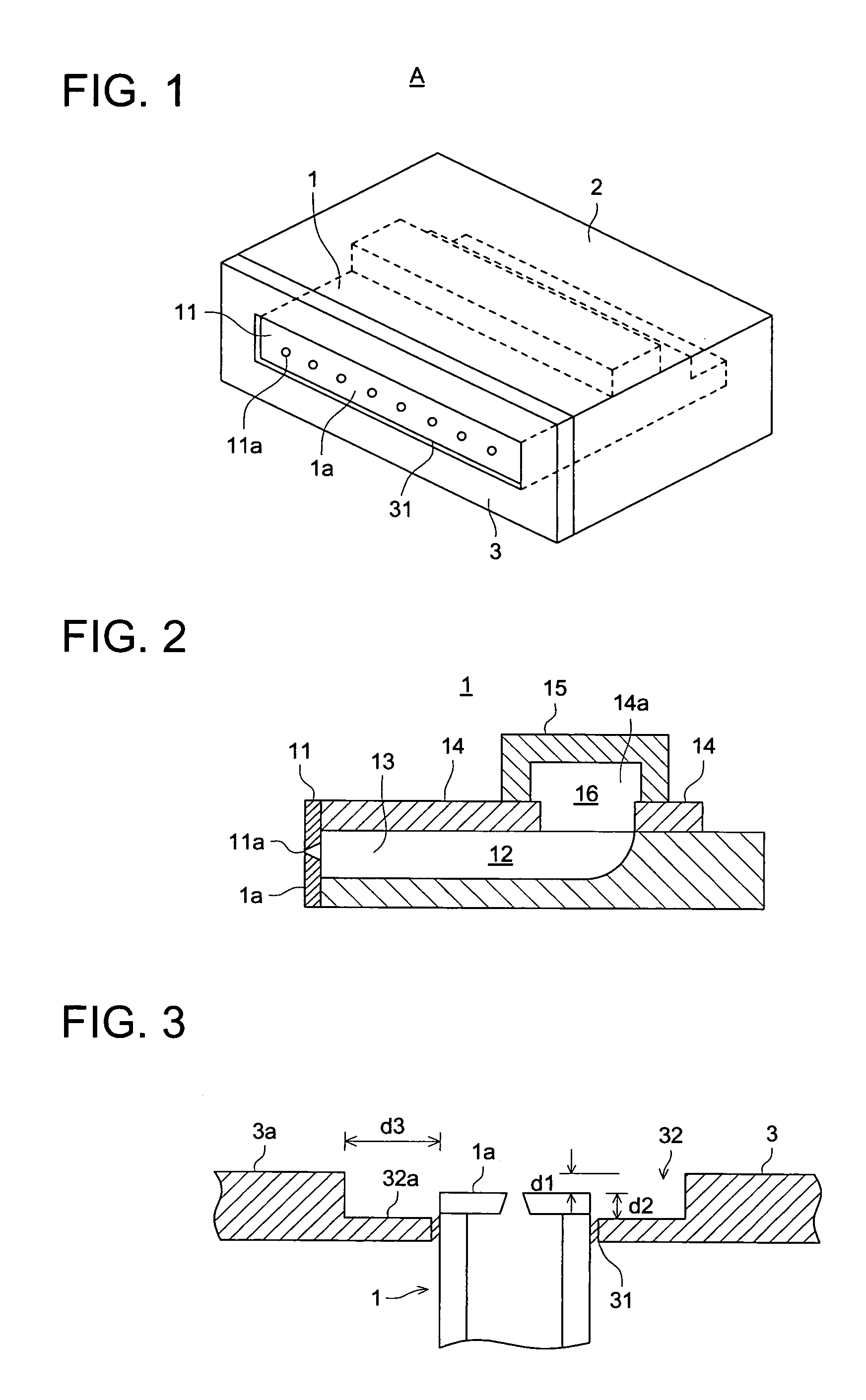
[0029]FIG. 1 is an external isometric view of an ink-jet head in accordance with the present invention, and FIG. 2 is a cross-sectional view principally showing the schematic structure of an actuator.

[0030]In FIG. 1, symbol A denotes the ink-jet head, and numeral 1 denotes the actuator. On the front face of the actuator 1, nozzle plate 11 provided with a number of disposed nozzles 11a for jetting ink is adhered. The actuator 1 comprises a non-piezoelectric ceramic substrate having a longitudinal shape and a number of parallel channels corresponding to the respective nozzles 11a, and a ceramic member that is arranged on the non-piezoelectric ceramic substrate and provided with piezoelectric ceramic layers having opposite polarization directions. The actuator 1 generates pressure change to be applied to ink.

[0031]Each channel 12 is formed by cutting the non-piezoelectric ceramic in a linear thin channel shape by a diamond blade or the like, wherein the remaining non-piezoelectric cera...


PUM


Abstract

An ink-jet head to jet ink from a front side thereof includes an actuator in which a plurality of parallel channels for generating pressure change to be applied to ink are formed and having a nozzle surface on which a plurality of nozzle holes are formed to jet ink from a corresponding ink channel, and a front plate located at the front side of the nozzle surface so as to protect the nozzle surface and having a recessed section on a front surface of the front plate, wherein the recessed section has an opening in which the nozzle surface of the actuator is inserted in such a way that the nozzle surface is located between the front surface of the front plate and the bottom surface of the recessed section.

Description

FIELD OF THE INVENTION[0001]The present invention relates to an ink-jet head for recording a desired image by jetting ink from nozzles onto a recording medium, wherein a front plate of the ink-jet head is improved. The front plate is applied to the surface of a nozzle plate to serve as a flat plate for protection of the nozzle surface, prevention of peeling of the nozzle plate, and providing a plane to have tight contact with a suction cap for sucking ink from the nozzles.BACKGROUND OF THE INVENTION[0002]An ink-jet head for recording a desired image by jetting ink from nozzles onto a recording medium is maintained, to be able to jet ink in a normal state all the time, in such a manner that: ink is periodically and forcibly subjected to suction from nozzles; thus high viscosity ink accumulated in nozzles is exhausted; and thereby blockage in nozzles is resolved.[0003]To suck ink as described above, it is necessary to cause a suction cap to tightly contact with the nozzle surface of t...

Claims


Application Information

Patent Timeline
Patent Type & Authority Patents(United States)
IPC IPC(8): B41J2/015B41J2/05B41J2/145B41J2/165B41J2/045B41J2/055B41J2/14
CPCB41J2/14209B41J2/1433
Inventor MAKITA, MASAHIRO
Owner KONICA MINOLTA INC
Why Eureka
Try Eureka